IM 439 / Page 3 of 24
Note: Installation and maintenance are to be performed only
by qualified personnel who are familiar with local
codes and regulations, and are experienced with this
type of equipment.
Sharp edges are a potential injury hazard. Avoid contact with
them.
Transportation and Storage
Upon receipt of the equipment, check unit for visible dam-
age. Make a notation on the shipper’s delivery ticket before
signing. If there is any evidence of rough handling, the
cartons should be opened at once to check for concealed
damage. If any damage is found, notify the carrier within 48
hours to establish your claim and request their inspection
and a report. The Warranty Claims Department should then
be contacted.
Do not stand or transport the machines on end. For storing,
each unit must be in the “up” position.
In the event that elevator transfer makes upended position-
ing unavoidable, absolutely ensure that the machine is in the
normal upright position for at least 24 hours before operating.
Temporary storage at the jobsite must be indoors, com-
pletely sheltered from rain, snow, etc. High or low tempera-
tures naturally associated with weather patterns will not
harm the conditioners. Excessively high temperatures 140°F
(60°C) may deteriorate certain plastic materials and cause
permanent damage. In addition, the solid-state circuit boards
may experience operational problems.
Installation
General
1. To prevent damage, this equipment should not be oper-
ated for supplementary heating and cooling during the
construction period.
2. Inspect the shipping label for any specific tagging numbers
indicated per request from the installing contractor. At this
time the voltage, phase and capacity should be checked
against the plans.
3. Check the unit size against the plans to be sure that the unit
will be installed in the correct location.
4. After removing the packaging material, remove unit from
the skid.
5. Before installation, check the available dimensions versus
the dimensions of the unit.
6. Pay attention to the location and routing of water piping,
condensate drain piping, and electrical wiring. The loca-
tions of these items are clearly marked on submittal
drawings.
7. The installing contractor will find it beneficial to confer with
piping, sheetmetal, ceiling and electrical foremen together
before installing any conditioners.
Note: Check the unit name plate for correct voltage with the
plans before installing the equipment. Also, make sure
all electrical ground connections are made in accor-
dance with local code.
8. We recommend that the contractor cover the conditioners
with plastic film to protect the machines during finishing of
the building. This is important if spraying fireproofing
material on bar joists, sandblasting, spray painting and
plastering operations have not been completed.
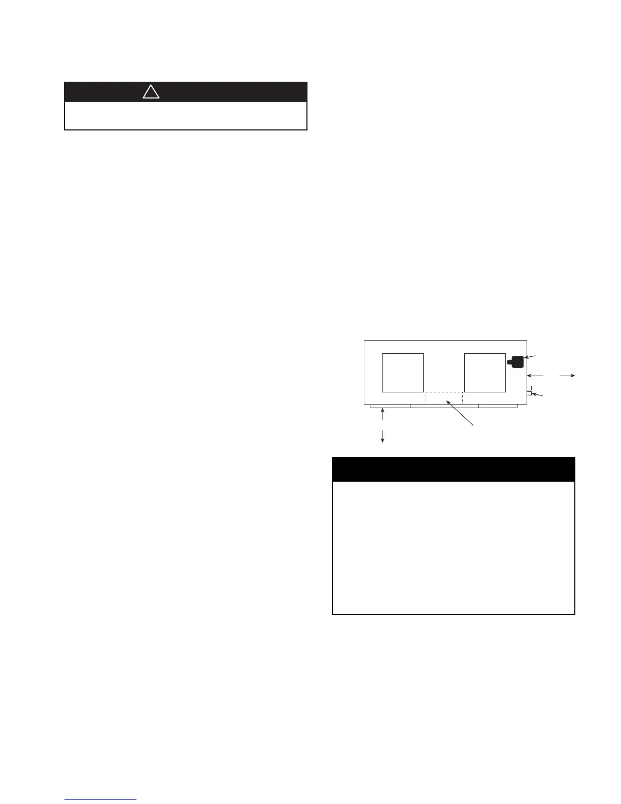
Control Box
Location
Piping
Location
Fan Motor
24"
(610 mm)
Side B
Side A
24" (610 mm)
Figure 1. Service clearance
1. A 24" (610 mm) minimum clearance is required on the
return air, control box and piping sides. However, a 36"
(914 mm) clearance allows for easier serviceability.
2. A 12" (305 mm) minimum clearance is required on Side
A to gain access to panel to remove locking collar for shaft
removal.
3. A 6" (152 mm) clearance is required on Side B to remove
screws holding top panel.
4. Top clearance is required for fan shaft removal.
5. Some codes dictate a 60" (1524 mm) clearance above
the control box which could be violated with a ducted
return. Check your codes.
Unit Location
1. Locate the unit in an area that allows for easy removal of
the filter and access panels, and has enough space for
service personnel to perform maintenance or repair. Pro-
vide sufficient room to make water, electrical and duct con-
nections
(see Figure 1 for service clearance details)
.
2. The contractor should make sure that access has been
provided including clearance for 2" (51 mm) thick filter brack-
ets, duct collars and fittings at water and electrical connec-
tions.
3. Allow adequate room around the unit for a condensate trap.
4. The unit can be installed “free standing” in an equipment
room. Generally, the unit is located in a separate room with
the non-ducted return air facing the return air intake. Alter-
natively, the unit can have a ducted return air.
5. It is recommended that the unit be located on vibration iso-
lators to reduce any vibration
(see Figure 3)
.
6. If optional field installed controls are required (Boilerless
System), space must be provided for the enclosure to mount
on the side of the unit.
CAUTION
!
IMPORTANT