IM 439 / Page 15 of 24
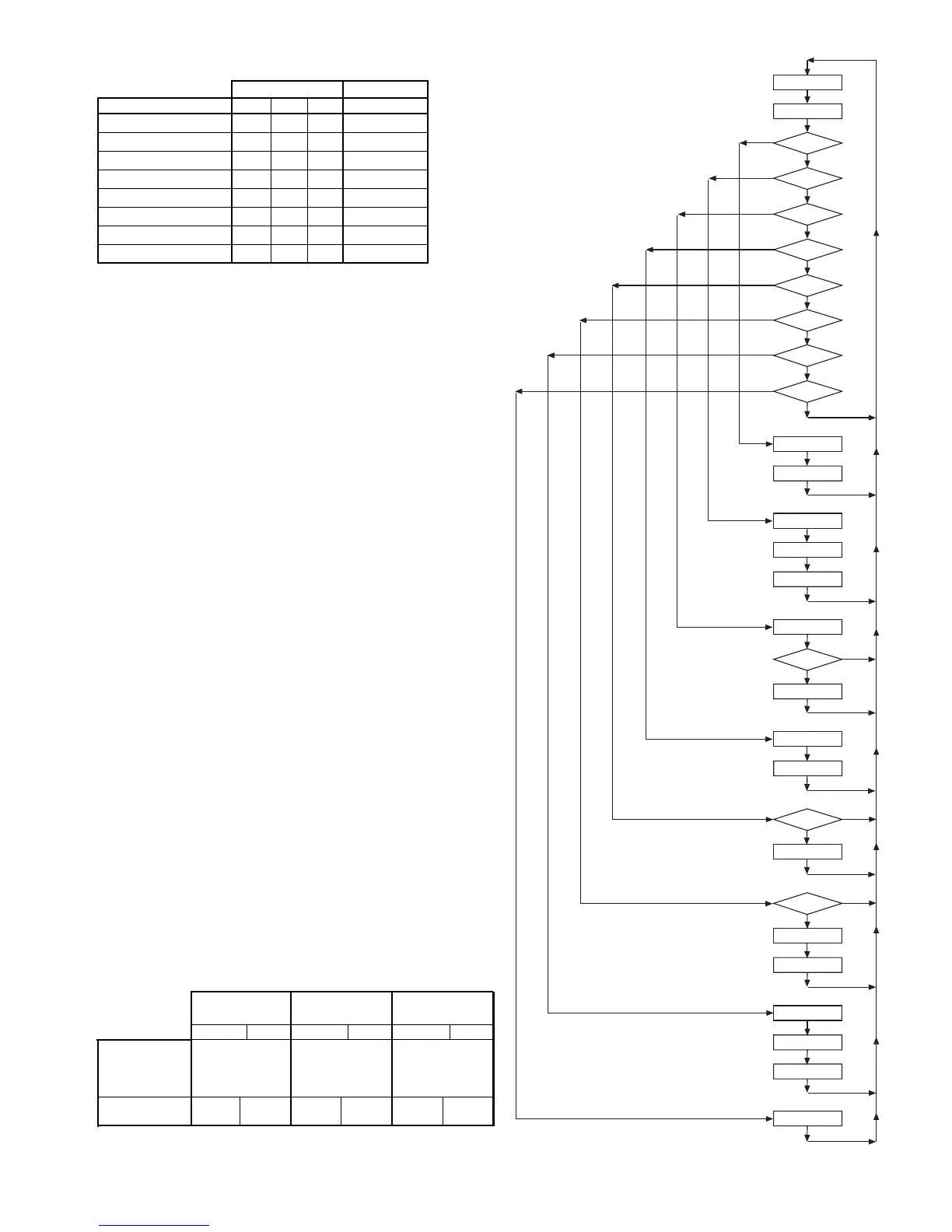
LED Status and Fault Output Status
Board Status LED’s Fault Output
Mode Yellow Green Red Terminal A
Occupied Off On Off Energized
Unoccupied On On Off Energized
Load Shed Off Off On Energized
Condensate Overflow On Dim Off De-Energized
High/Low Pressure Fault Off Off Flash De-Energized
Low Temperature Fault* Flash Off Off De-Energized
Brownout Off Flash Off De-Energized
Emergency Shutdown Off Flash Off De-Energized
*in heating mode only
Read Outputs
Check Timers
Hi
Pres. Sw ?
Brown Out ?
Low Temp Sw ?
Lo Shed ?
N S B ?
Cond. Overflow?
R - W 1 ?
R -Y 1 ?
Stop Comp.
Flash Red LED
Stop Fan
Flash Green LED
Stop Comp.
Htg Mode?
Stop Comp.
Flash Yellow L E D
Stop Comp.
Turn On Red LED
R - W 2 ?
Start Comp.
Cooling Mode
Turn On Yellow LED
Stop Comp.
Reversing Valve On
Time Delay
Start Comp.
Start Comp.
No
No
Yes
No
Yes
No
No
No
No
No
No
No
No
Yes
Yes
Yes
Yes
Yes
Yes
Yes
Yes
General Use and Information
The Mark IV/AC control board is provided with three drive terminals,
R(24vac), F(24vdc), and C(Ovac) that can be used by the end user to
drive the thermostat inputs (G, Y1, W1, and W2) and control inputs
(U, L, E, and O). Any combination of a single board drive terminal (R,
F, or C) may be used to operate the Mark IV/AC boards control or
thermostat inputs. However, only one drive terminal (R, F, or C) can
be connected to any individual input terminal or damage will occur.
Some of the control inputs are used within the Water Source Heat
Pump and not accessible to the end user. For example, HP, LT, and
COF are not available for use by the end user.
Typically the Mark IV/AC board’s R(24vac) terminal is used to drive
the board’s thermostat inputs and control inputs by connecting it to
the R terminal of an industry standard thermostat. The control out-
puts of the standard thermostat are then connected to the Mark IV/
AC board thermostat inputs and control inputs as needed. Any re-
maining board input(s) may be operated by additional thermostat out-
puts or remote relays (dry contacts only).
All Mark IV/AC board inputs must be operated by dry contacts pow-
ered by the control board’s power terminals. No solid state devices
(Triacs) may be used to operate Mark IV/AC board inputs. No outside
power sources may be used to operate Mark IV/AC board inputs.
Note: The fault output is energized when no faults exist. The fault output is
de-energized during faults and when unit power is off.
Using Drive Using Drive Using Drive
Terminal R (24vac) Terminal F (vdc) Terminal C (ground)
De-energized Energized De-energized Energized De-energized Energized
Place the Meters
Place the Meters Place the Meters Place the Meters
Red (+) Lead on
on Black (-) Lead Black (-) Lead Black (-) Lead
Input to be
on C on V on R
checked
U, L, E, Y1, W1,
10 to 22 to
0vdc
30 to 10 to 22 to
G, W2, O 14vac 26vac
33vdc
14vac 26vac
Remote Reset of Manual Lockouts – The Remote Reset feature
provides the means to remotely reset automatic lockouts generated
by high-pressure and/or low-temperature (in heating) faults. When
the Mark IV board is in automatic lockout due to one of these faults,
and the cause of the fault condition has been alleviated, energizing
the O-terminal for 10 seconds or more will force the Mark IV board to
clear the lockout. A unit power cycle can also be used to clear an
automatic lockout if the conditions causing the fault have been allevi-
ated.
Fault Retry To Minimize Nuisance Trips – The Fault Retry feature
helps to minimize nuisance trips of automatic lockouts caused by
high-pressure and/or low-temperature (in heating) faults. This feature
clears faults the first two times they occur within a 24-hour period and
triggers an automatic lockout on the 3rd fault. The retry count is reset
to zero every 24 hours.