IM 439 / Page 5 of 24
Air Balancing
All units are supplied with a variable pitch motor sheave to aid
in airflow adjustment. They are typically set at the low end of
the rpm range for field adjustment to the required airflow.
When the final adjustments are complete, the current
draw of the motors should be checked and compared to the
full load current rating of the motors. The amperage must not
exceed the service factor stamped on the motor nameplate.
Upon completion of the air balance, it is a common
industry recommendation that the variable pitched motor
sheave be replaced with a properly sized fixed sheave. A
matching fixed sheave will provide longer belt and bearing
life and vibration free operation. Initially, it is best to have a
variable pitched motor sheave for the purpose of air balancing,
but once the balance has been achieved, fixed sheaves
maintain balancing and alignment more effectively.
Adjustment (See Figure 6)
1. All sheaves should be mounted on the motor or driving
shaft with the setscrew “A” toward the motor.
2. Be sure both driving and driven sheaves are in alignment
and that shafts are parallel.
3. Fit internal key “D” between sheave and shaft, and lock
setscrew “A” securely in place.
Adjusting:
1. Loosen setscrews “B” and “C” in moving parts of sheave
and pull out external key “E”. (This key projects a small
amount to provide a grip for removing.)
2. Adjust sheave pitch diameter for desired speed by open-
ing moving parts by half or full turns from closed position.
Do not open more than five full turns.
3. Replace external key “E” and securely tighten setscrews
“B” over key and setscrews “C” into keyway in fixed half of
the sheave.
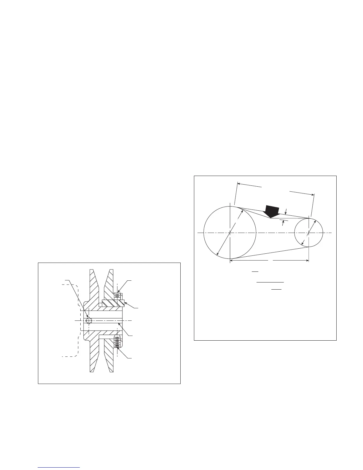
Figure 6.
Figure 7. Drive belt adjustment
“E”
“B”
“D”
“C”
“A”
Single Groove
Key “E” projects to
provide a grip for
removing.
h=
t
64
t= C
2
–
D-d
√
2
()
Where:
t= Span length, inches (mm)
C= Center distance, inches (mm)
D= Larger sheave diameter, inches (mm)
d= Smaller sheave diameter, inches (mm)
h= Deflection height, inches (mm)
Note: The ratio of deflection to belt span is 1:64.
Deflection
Force
h
D
d
Span Length (t)
C
4. Put on belts and adjust belt tension to 4 lbs. ± 0.7 lbs.
(18 ± 3N) for a
1
⁄2" to
3
⁄4" (13 mm to 19 mm) belt deflection
height.
5. To determine the deflection distance from normal position,
use a straightedge or stretch a cord from sheave to sheave
to use as a reference line. On multiple-belt drives an adjacent
undeflected belt can be used as a reference.
6. Future adjustments should be made by loosening the belt
tension and increasing or decreasing the pitch diameter
of the sheave by half or full turns as required. Readjust belt
tension before starting drive.
7. Be sure that all keys are in place and that all setscrews are
tight before starting drive. Check setscrews and belt tension
after 24 hours service.
8. When new V-belts are installed on a drive, the initial
tension will drop rapidly during the first few hours. Check
tension frequently during the first 24 hours of operation.
Subsequent retensioning should fall between the mini-
mum and maximum force.