106
FIELD PIPING
To ensure satisfactory operation and performance, the following points should be noted for the field piping
arrangements of the complete refrigerant cycle.
a) Liquid loops or oil traps must be provided according to the position of the outdoor and the indoor units (depending on
whether the indoor unit is above or below the outdoor unit).
b) Field supplied filter dryer should be provided as close to the expansion valve(s) of the indoor unit (evaporator) as
possible.
c) Field supplied sight glass must be assembled and mounted next to filter dryer.
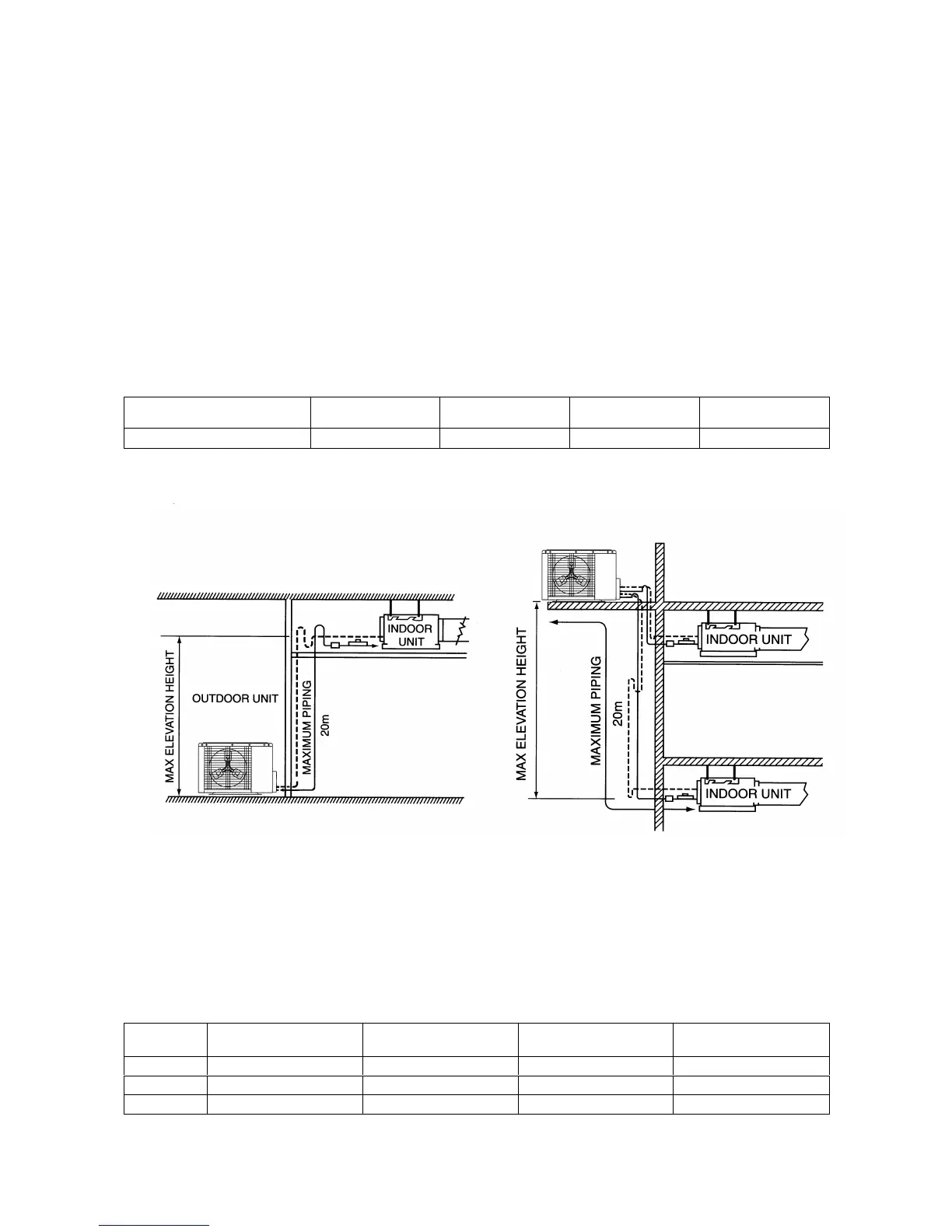
MAXIMUM PIPE LENGTH AND MAXIMUM NUMBER OF BENDS
When the pipe is too long, the required refrigerant quantity increases. Both the capacity and reliability drops as a result.
As the number of bends increases, system piping resistance to the refrigerant flow increases, thus lowering the cooling
capacity and the compressor may become defective. If the height difference between the evaporator and the condenser
is excessive, the cooling capacity drops, the lubricating oil return is retarded, affecting the compressor efficiency
adversely.
Always choose the shortest piping path and follow the recommendations as shown below :
Model Max. Elevation, m
(ft.)
Max. Length,
M (ft)
Max. Total
Length, m (ft.)
Max. of Bends
MMC 075/100/125/150D/DR 20(65.6) 15 (49.2) 35(114.8) 8
CAUTION:
1) Our guarantee on the performance of our air-conditioners is strictly revoked if the height, length and/or the
number of bends of the refrigerant piping system installed is beyond the limit above.
2) Bendings must be carefully made so as not to crush the pipe. Use a pipe bender to bend a pipe as far as
possible.
Maximum Allowable Piping Length & Elevation Difference
INSTALLATION CLEARANCE
A) For MMC – D/DR series (Single/Multiple Condensing Unit)
When two or more outdoor units are installed in a location, they must be positioned such that one unit will not be taking
the hot discharge air from another to avoid hot air short circuiting.
This also applies when two or more units are installed one above the other. Below are the installation clearance
guidelines :
Model MMC 075/100/125/150D/DR
2 x
MMC 075/100/125/150D/DR
3 x
MMC 075/100/125/150D/DR
4 x
MMC 075/100/125/150D/DR
A (mm) 300 600 600 600
B (mm) 1000 1000 1000 1000
C (mm) 1500 1500 2000 2000