118
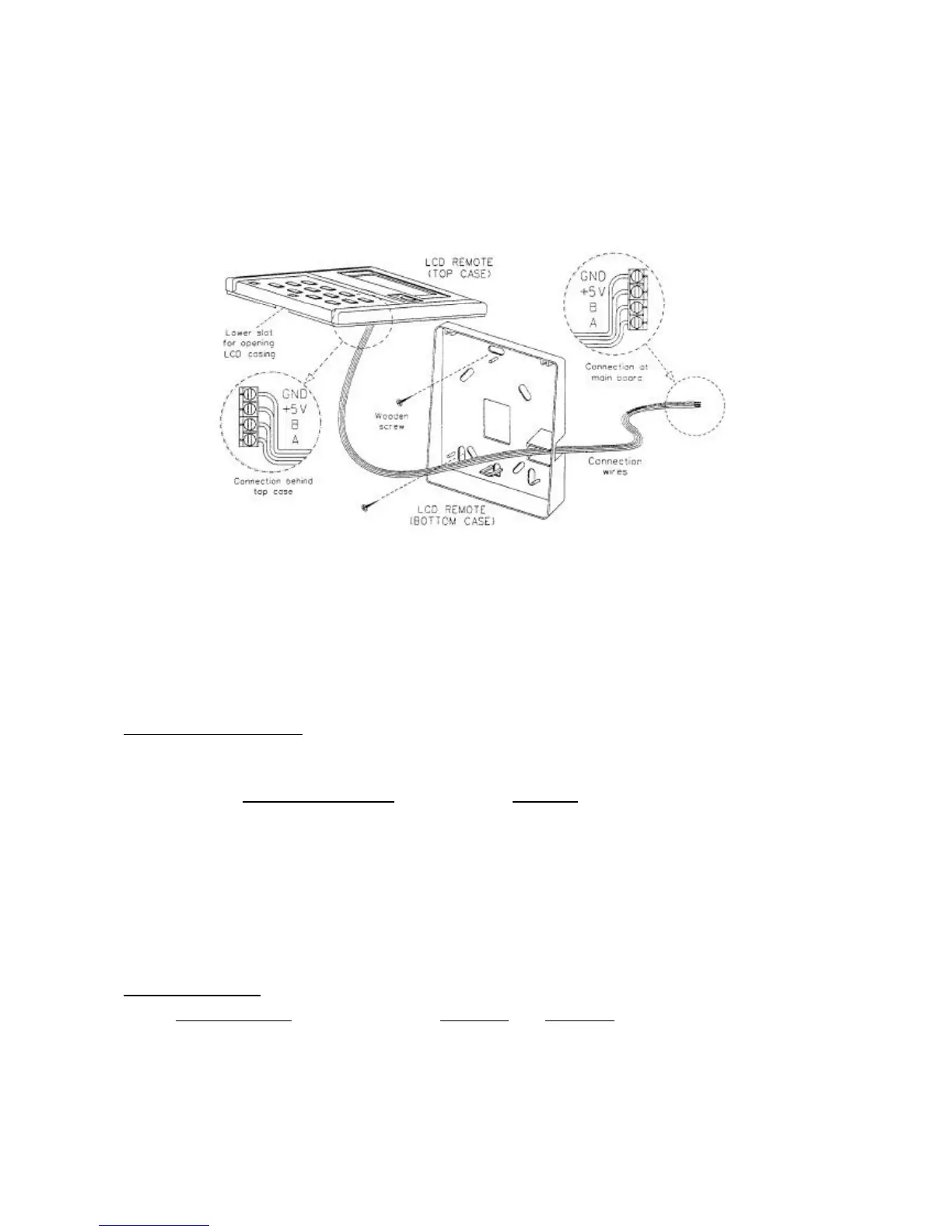
ii) Fix the bottom case onto the wall with the 2 wooden screws provided. Then, insert the 4 connecting
wires (from the main board) through the slot on the lower right.
iii) Connect one end in each of the 4 wires to the terminal block behind the top case as shown below.
The wire that goes into the "GND" terminal at the top case must be connected at the other end to the
“GND" terminal at the main board. The same goes for the "+5V", "B" and "A" connection.
iv) Fasten back the top and bottom case into place. Hook the two upper claws into their respective slots
and snap the lower part shut.
5. AUTO RANDOM RESTART
When power resumed, the unit will automatically restart and operate at the previous setting as before power
failure occurred. (Remove jumper at JH/JP1 will cancel the auto random restart function. Please refer to
wiring diagram for the location of the JH/JP1).
SEQUENTIAL CONTROLLER SPECIFICATIONS
The controller can be configured to suit individual’s need with details below :
Model Selection
1. Number of Compressor
The control can be configured into 6 main types base on number of compressors
by changing “R42” values :
Number of Compressor R42 value
a. Cooling / heater* 2 Compressor 20k
b. Cooling / heater* 3 Compressor 47k
c. Cooling / heater* 4 Compressor Open
d. Heat pump 2 compressors 1k
e. Heat pump 3 compressors 3.3k
f. Heat pump 4 compressors 9.1k
Note : * Cooling or heater model depending on SW1 and SW2 setting. Factory setting for number of
compressor is based on air conditioner models.
2. Number of Heater
Number of Heater SW1(dip1) SW2(dip2)
a. No heater (0 heater) off off
b. 1 heater on off
c. 2 heaters on / off on
Note : Factory preset : SW1 = off; SW2 = off ~ no heater