EasyManua.ls Logo

McQuay SWT C Series User Manual

McQuay SWT C Series
44 pages
To Next Page IconTo Next Page
To Previous Page IconTo Previous Page
Page #5 background image
IM709 5
Disassembly of Sections
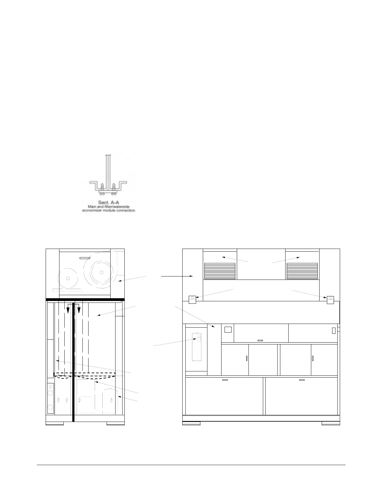
If units are ordered for modular construction, they may be
easily disassembled into three sections. The figures below
illustrate the main cooling/heating, filter/waterside econo-
mizer, and fan sections. The thick lines in the figures show
where the sections are disassembled. The section are secured
by connection plates and screws. The following information
describes the location of the connecting points.
Fan section — base sections disassembly
The fan section sits on the base sections and is secured with
four steel plates. Each plate has two screws in the base sec-
tions and two screws in the fan section. Two of the plates are
shown in Figure 3. The connection plates are also the rigging
plates for the fan section only. They must not be used for rig-
ging the entire unit.
Main cooling/heating — filter/waterside economizer
sections disassembly
The following information is for units ordered for modular
construction (code 32=1). Note: The disassembly of units
not ordered for modular construction (code 32=Y) will
require field modification. Units not ordered for modular
construction do not have victaulic couplings on the water
pipes and the various control sensors are mounted in the unit.
Two steel plates the height of the sections connect the
main cooling/heating and the filter/waterside econo-
mizer sections. The plates are secured with multiple
screws on the right and left side of the base sections.
The connection plate and screws are illustrated in Sect
A-A.
The filter/waterside economizer section overlaps the
main cooling/heating sections along the bottom and top
adjoining rails. Multiple screws connect the two sec-
tions along these bottom and top overlaps.
Victaulic couplings connect the water pipes between the
filter/waterside and main cooling/heating sections. Each
victaulic coupling is secured with two bolts
.The condensate drain pipe between the two sections is
connected by a flexible PVC tube with pipe clamps.
Fan
Outlets
FILTER SECTION
EVAPORATOR
HEATER
ELECTRICAL PANEL
ECONOMIZER
AA
Fan
Section
Main Cooling/
Heating Section
Filter/Waterside
Economizer
Section
Condenser
Compressor
Connection Plates
(2)
Figure 2
Figure 3
(1) Unit sizes 018, 023 and 028 have a single fan.
(2) Connection Plates are also the Rigging Plates for the Fan Section only.
ASD
(Optional)

Table of Contents

Question and Answer IconNeed help?

Do you have a question about the McQuay SWT C Series and is the answer not in the manual?

McQuay SWT C Series Specifications

General IconGeneral
BrandMcQuay
ModelSWT C Series
CategoryAir Conditioner
LanguageEnglish

Summary

Installation Procedures for Air Conditioning Units

Refrigerant Piping and Safety Precautions

Water Connections and Piping Guidelines

Condenser Piping Installation

Details on connecting condenser water supply and return lines.

Field Wiring Guidelines

Power Supply and Wiring Requirements

Supply Power Wiring and Voltage

Requirements for three-phase power supply and voltage tolerances.

Disconnect and Lug Sizing

Information on single disconnect and power block lug sizes.

Control Center Layout and Components

High and Low Voltage Compartments

Description of the control center's layout and housed components.

Typical Wiring Schematics Overview

Power Schematic Diagram

Diagram illustrating the unit's power wiring connections.

Standard Unit Controls and Safety Features

High Pressure Switches

Function and operation of high pressure safety switches.

Low Pressure Switches

Function and operation of low pressure safety switches.

Compressor Motor Protector

Description of thermal protection for compressor motors.

Proof of Airflow Switch

Operation of the airflow proving switch for fan safety.

Frost Protection Switches

Function of frost protection switches to prevent coil freezing.

Clogged Filter Switch

Operation of the clogged filter switch for filter replacement indication.

Unit Options and Special Features

Additional Unit Options and Features

System Check, Test, and Start Procedures

Fan Start-up Procedure

Steps to start and verify the supply air fan operation.

Variable Air Volume (VAV) Start-up

Adjusting VAV parameters for optimal airflow control.

Pre Start-up Checks

Pre-operational checks before unit startup.

Compressor Start-up Procedure

Steps for starting compressors and verifying operation.

Initial Unit Start-up

Steps for initial unit startup and verification.

Expansion Valve Superheat Adjustment

Procedure for adjusting expansion valve superheat for optimal performance.

Refrigerant Charge Calculation and Verification

System Maintenance and Servicing

Preventative Maintenance Schedule

Routine maintenance tasks to ensure optimal system performance.

Replacement Parts Identification

Service and Warranty Procedures

Product Warranty Terms

Details on the company's product warranty coverage.

System Check, Test, and Start Form

Start-up Procedures Checklist

Checklist for verifying start-up operations.

System Check, Test, and Start Form Readings

Compressor Readings and Settings

Fields for recording compressor performance data.

System Check, Test, and Start Form Controls

Related product manuals