10 WGS 130A to 190A OM WGS-5
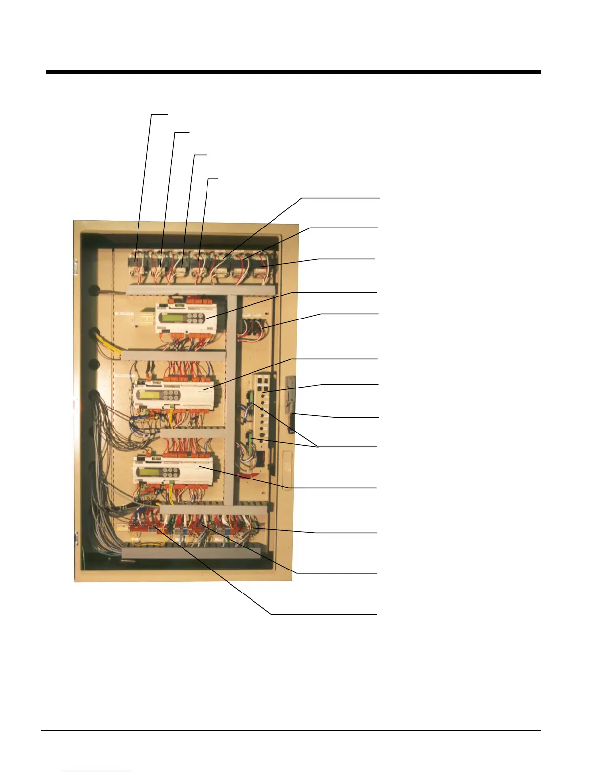
Control Panel Layout
Figure 3, Outer (Microprocessor) Panel
NOTES:
1. Transformers T2 through T25 are class 100, 120V to 12V.
2. Switches for MHPR 11 and 12 (Mechanical High Pressure Switches) are located on the compressors.
3. Mechanical High Pressure Switches Open at 310 psi, Close at 250 psi.
T2
Unit Controlle
T13, Circ#1 Controller
T14, Circ#1 Load Solenoid
T15, Circ#1 EXV Power
T25, Circ#2 EXV Power
T24, Circ#2 Load Solenoid
T23
Circ#2 Controlle
Unit Controller
MHPR11 &12, Mechanical
High Pressure Relay
Circ#1 Controller
Circuit Breaker &
Switch Panel
Circ#1 & 2 EXV Drivers
External Disconnect Handle
Circ#2 Controller
TB3, Circ#2 Controller
Terminal Board
TB2, Circ#1 Controller
Terminal Board
TB1 Unit Controller
Terminal Board
 Loading...

