Gas side (k)f
(Liquid side fJ)
Wiring hole ( )
f38
)
Drainage pipe installation hole (f32
Humidifier hole (inside)
80
300
185
200
140
73
170
100
240
128
II
Below the ceiling
Panel
Hole
Hook(on Field)
7
30
106
30
138
39
20
G
106
130
130
200
32 18
(f100)
Hole
Below the ceiling
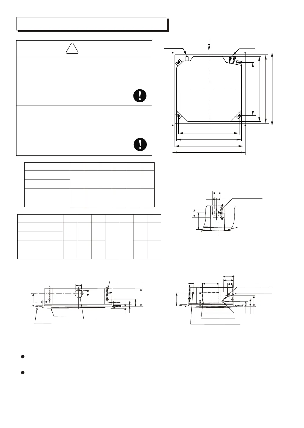
INDOOR UNIT INSTALLATION
A
Drain side
Piping side
800 (Hook-location)
D(Hook-location)
800 (Body)
C (Body)
880(Ceiling hole)
B (Ceiling hole)
940 (Panel)
A(Panel)
Please select a place where sound enough
to bear the indoor unit when installation
The Indoor Unit is possible to fall if the place
is not sound enough.
To take precautions against typhoon/earth
quake.
Be sure to install strictly according to related
specification. Wrong installation will
cause the unit to fall.
!
CAUTION
4
Model(MDV-D)
ABCDEF
940
1350
880
1290
820
1230
620
1030
405
610
400
605
28~36Q4/N2
71~80Q4/N2
90~112Q4/N2
GHIJKLM
260
320
536
946
130
180
f9.5
f19.0
196
136
246 186
28~45Q4/N2
56~80Q4/N2
90~112Q4/N2
Model(MDV-D)
Select installation location considering piping and wiring connection after the Indoor Unit has
been hanged. Then decide the piping wiring leading direction.
Be sure to lead the refrigerant pipes, drain pipes and connection wires out to its connection
location before hanging the unit if the opening on the ceiling has been decided.
Confirm sizes of the indoor unit and ceiling opening with the attached installation paper
pattern. (Please fix the paper pattern below the body with M5X16 screws (4).)