Mounting the Telescope on the Ultrawedge
1. Thread one of the provided mounting screws into the hole
on the underside of the telescope dr
ive base. The desired
hole is located at the curved end of the telescope drive
base.
2.
Grasp the two fork arms of the telescope firmly, with the
control panel toward you, place the telescope onto the
wedge tilt plate (1, Fig. 1) by sliding the mounting screw
on the telescope base into the slot at the top tilt plate (
4,
Fig.1).
3. Insert the two remaining provided mounting screws
through the underside of the tilt plate (
10,
Fig.
1
) and into
the underside of the drive base. Firmly tighten the screws.
Do not overtighten.
4. Insert the T-bolt (1,
Fig. 4
) through the center of the
underside of the tilt plate and into the underside of the
drive base. Firmly tighten the bolt. Do not overtighten.
Note:
It is important to insert the T-bolt into the
wedge-telescope assembly. The T-bolt insures the
precise pointing accuracy of the Ultrawedge.
The telescope is no
w fully mounted onto the wedge and tripod.
Adjustments in wedge latitude angle and/or azimuth orientation
may be made with the telescope in place.
Setting the Obser
ving Latitude
Look up the latitude of the desired observing site (most road
maps show latitude lines). Then, loosen the attachment screws
(2, Fig. 1) and rotate the fine latitude control knob (3, Fig. 1)
while reading the latitude scale (6, Fig. 1). The latitude pointer
is a v
er
nier scale (
5,
Fig.
1
) which will allo
w the tilt angle to be
set to within 0.25°. When the tilt plate is aligned with the desired
latitude, tighten the attachment screws.
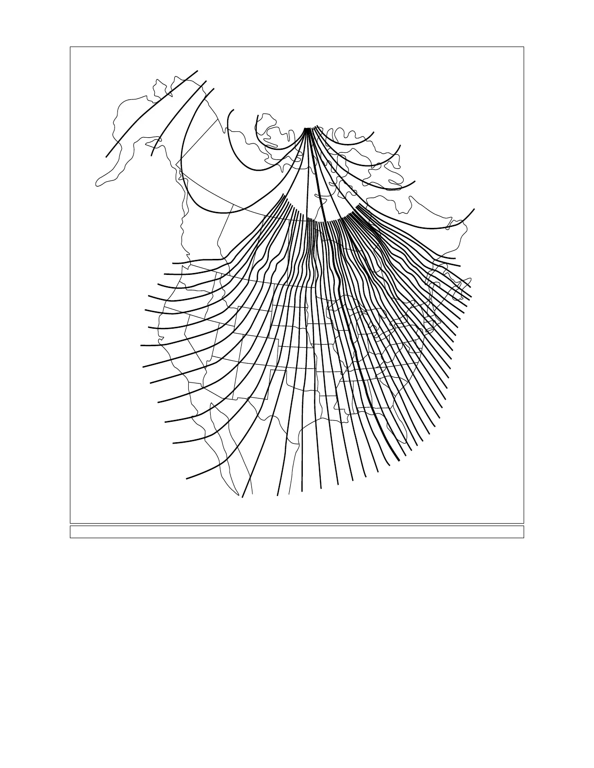
Aligning the Magnetic Compass
With the aid of the magnetic compass, a telescope can be polar
20°
25°
30°
40°
50°
60°
50°
40°
30°
25°
24°
23°
22°
21°
20°
19°
18°
17°
16°
15°
14°
13°
12°
11°
10°
9°
8°
7°
6°
5°
4°
3°
2°
1°
0°
1°
2°
3°
4°
5°
6°
7°
8°
9°
10°
15°
16°
17°
18°
19°
20°
21°
22°
14°
13°
12°
11°
E — Declination — W
Fig.
5:
Ma
gnetic Declination Map.
2