DER2 digital regulator instruction manual - rev. 02 - pag. 30
The status of active alarms is stored at location L[38], which can be read with the USB connection.
The index of bits that have a value of 1 corresponds to the active alarm. If the regulator is correctly working
(no alarm active) the bit 11 will be high.
CONTROLLING OF REGULATOR ALARMS
N. Description of event Action
1 Checksum EEprom Reset default data - Blockage
2 Over voltage (at rated speed) APO
3 Under voltage (at rated speed) APO
4 Short circuit APO, Maximum current - Blockage
5 Excitation Overcurrent APO, Reduction of excitation current
6 Underspeed APO, V/F Ramp
7 Overspeed APO
TABLE 12 : ALARMS LIST
8 Underexcitation / loss of excitation APO
TABLE 13 : ALARM FLAGS AT LOCATION L[38]
B
15
B
14
B
13
B
12
B
11
B
10
B
9
B
8
B
7
B
6
B
5
B
4
B
3
B
2
B
1
B
0
32768 16384 8192 4096 2048 1024 512 256 128
64 32 16 8 4 2
1
A12 A11 A10 A9 A8
A7 A6 A5 A4 A3 A2
A1
J50/60 - Reserved
Reserved
OK - - - Underexcitation Over
speed
Under
speed
Over Excitation Short Under
voltage
Over
voltage
Check sum
EEPROM
Location L[38] (third “STATUS” box)
Example:
Location 38 = 48 = 0000000000110000
2
: it means that Bits B5 and B4 are at 1, therefore alarms A6 and A5
are active.
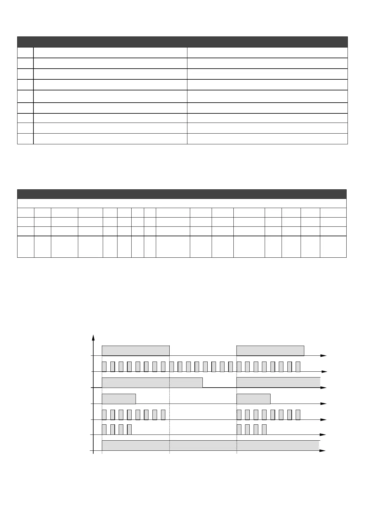
1. Alarm signals with the indicator lights
During normal operation and a duty cycle of 50% (OK in fig. 11) an indicator light mounted on the board
flashes every 2 seconds; it flashes differently in the event of intervention or alarm, as indicated in fig. 11.
OK
CHECKSUM
SHORT CIRCUIT
Hz or O.S.
MP
MP and (Hz or O.S.)
STOP
llarm intervention
1
2t [sec]
LED
LED ON
LED OFF
LED ON
fig.12
 Loading...