Do you have a question about the Mecc Alte DER2 and is the answer not in the manual?
Describes the DER2 regulator as part of a two-component system (regulator and supervision unit).
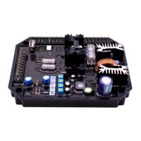
Details the digital regulator's features, power, and environmental specifications.
Lists and specifies the terminal connections and their functions for the regulator.
Illustrates the internal connections and signal flow within the DER2 regulator.
Explains the module that allows faster reduction of excitation current for reduced transient overvoltage.
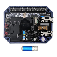
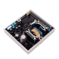
Provides dimensional drawings and mounting information for the DER2 regulator.
Details the importance of correct connections and potential consequences of errors.
Details DER2 connections for typical applications and voltage sensing.
Explains how to set up the regulator using trimmers, jumpers, and software parameters.
Lists parameters, their ranges, default values, and notes for configuration via ModBus.
Covers setting output voltage, soft start, and slow voltage variations.
Explains adjustment of stability and proportional/integral gain settings.
Explains the excitation temperature estimator and overcurrent protection function.
Details the procedure for calibrating overload protection using a supervision unit.
Provides steps for calibrating overload protection without supervision equipment.
Explains how machine voltage is regulated proportionally to frequency below a set threshold.
Outlines the procedure to calibrate underspeed protection with a supervision unit.
Describes how to calibrate underspeed protection without supervision equipment.
Explains voltage reduction limits as a function of frequency and parameter P[14].
Describes how parameter P[24] sets the voltage/frequency slope during startup.
Defines the operating time with the alternator short-circuited before regulator blockage.
Details the low excitation/loss of excitation alarm and its recognition via location L[56].
Describes how indicator lights signal normal operation, intervention, and alarms.
Details specific alarms, their causes, actions, and APO output status.
Explains the APO output status and how alarms trigger it.
Describes how to obtain the total operation time of the regulator from alarm data.
Provides diagrams for functional checkout and parameter setting on a test bench.
| Voltage Regulation Accuracy | +/- 0.5% |
|---|---|
| Maximum Output Current | 7A |
| Frequency | 50/60 Hz |
| Output Voltage | 0-90V DC |
| Output Current | 7A |
| Humidity | 95% non-condensing |
| Operating Temperature | -40°C to +70°C |
| Storage Temperature | -40°C to +85°C |
| Stability | ±0.5% |