DER2 digital regulator instruction manual - rev. 02 - pag. 18
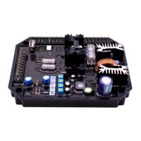
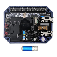
Fig. 5a: 100K external potentiometer connection Fig. 5b: 25K external potentiometer connection
9. VOLT, STAB, Hz and AMP Trimmers
The trimmers are enabled by the software DxR_Terminal; if they are not enabled, they do not perform any
function.
The VOLT trimmer allows adjustment from about 75V to about 150V or from about 150V to about 300V.
The STAB trimmer adjusts the dynamic response (statism) of the alternator under transient conditions.
The Hz trimmer allows for a variation of the "low speed protection" of up to –20% with respect to the
nominal speed value set by the 50/60 jumper (if activated) or by the 50/50 box in the Settings/
UFLO&LAM menu (at 50 Hz the threshold can be calibrated from 40 Hz to 50 Hz, at 60 Hz the threshold
can be calibrated from 48 Hz to 60 Hz).
The AMP trimmer adjusts the excitation overcurrent protection intervention threshold.
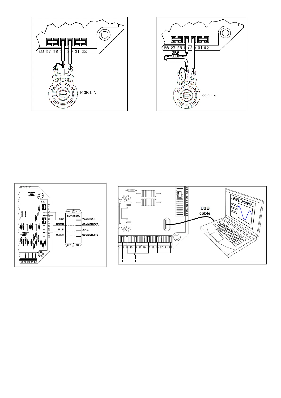
10. USB Communications
The COM connector is RESERVED for connection to supervision unit through the dedicated USB cable (see
fig. 7).
For the communication, the regulator implements a subsystem of the ModBus standard; the DER2 performs
a “slave” operation the address of which is stored in the DER2 EEPROM and is set during configuration.
Detailed descriptions of the ModBus commands implemented are into the Technical Guide “Digital Regula-
tors Comunication Protocol” available on the web site www.meccalte.com.
The “Master Unit” is made up of a PC or other dedicated equipment and can access the parameters and
functions of the regulator.
The master unit has the following possible functions:
Repetition, or visualisation, of the generator status variables, even from a remote location
Setting of single parameters
Uploading and downloading of settings files
Status readings (alarms, measuring variables)
Readings of the alarm memory information
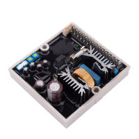
Fig. 6: Connessione filtro EMI SDR182/K
Fig. 7: Connessione tra DER/1 e PC tramite interfaccia digitale USB2DxR
 Loading...