DER2 digital regulator instruction manual - rev. 02 - pag. 19
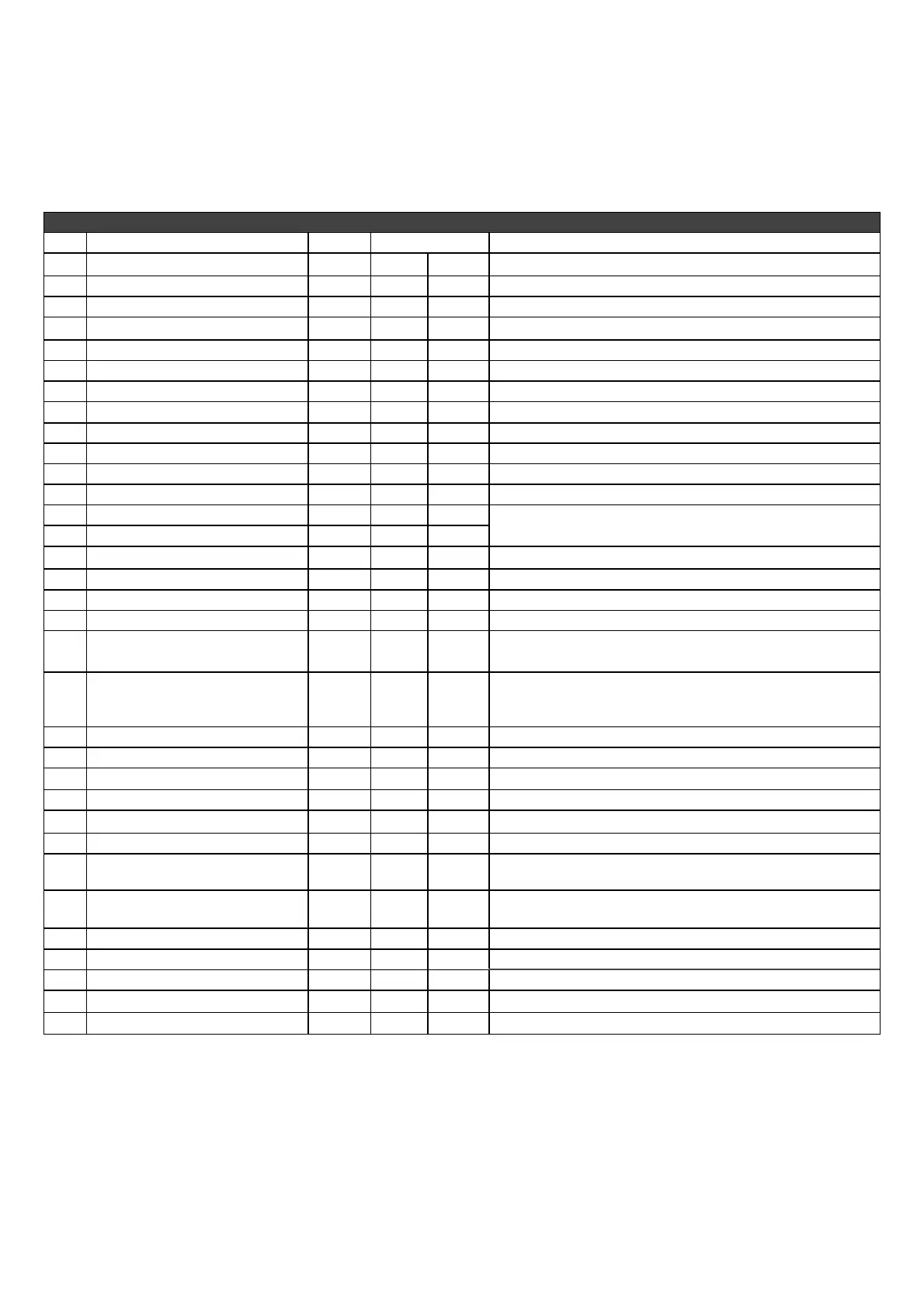
TABLE 6 : EEPROM SETTING REGISTRIES
Add.
Description of Parameter Range
NOTES
DER2 DER2/A
0 Firmware revision
0..65535
22 22 Reserved - Do not write
1 ModBus slave address
1..31
1 1 Identification of RS485 network (or broadcast)
2 Software configuration
0..65535
17426 19218 Reserved - Do not write
3 Serial number, high part
16bit
0 0 Reserved - Do not write
4 Serial number, low part
16bit
0 0 Reserved - Do not write
5
Three phase sensing calibration 0..32767
16384 16384 Calibration of voltage channels in 3 ph adjustment
6
Single Phase sensing calibration 0..32767
16384 16384 Calibration of voltage channels in 1 ph adjustment
7 Measured voltage calibration
0..32767
16384 16384 Calibration of location L 36 (first “STATUS” box)
8 Current limit time
0..32767
0 0
Duration of limiting in number of periods
9 Current limit level
0..32767
32767 32767 Excitation voltage limit upon start-up
10 Word configuration
16bit
7988 7988 Detailed descriptions paragraph 2 table 7
11
Shift to LEFT proportional gain 0..6
4 5
n=0…6 is equivalent to a multiplication by 2
n
12
Shift to LEFT integral gain 0..6
3 1
namely 1, 2, 4, 8, 16, 32, 64.
13 Coefficient tieing Ki to Kp
0..32767
16384 26624 Coefficient to set Ki and Kp separately
14 Vout / Vaux Ratio
±32767
6000 6000
Limit to voltage reduction as a function of frequency
15
Reference equivalent to Vext 0..32767
16384 16384
Value used if the Vext input and location L[49] are disabled
16
Limitation of Vext Variation 0..6553
4608 4608
Limits the effect of external analogical input (0->0; 4608->14%)
17
APO delay & alarm settings 0..65535
254 254
Selects alarms that activate the APO contact and sets the delay
intervention
18 Step limitation reference
1..1000
50 50
For rapid variations of voltage setpoint, the passage from one
value to another takes place through added or subtracted steps at
each period.
19 Vout Reference
0..32767
0 0
Value used if the VOLT trimmer is disabled
20 Stability
0..32767
16384 16384
Value used if the STAB trimmer is disabled
21
Freq. threshold 10% freq
nom
0..32767
26214 26214
Value used if the Hz trimmer is disabled
22
Excitation overcurrent threshold 0..32767
16384 16384
Value used if the AMP trimmer is disabled
23
V/F Slope 0..32767
1875 1875
V/F curve slope during normal operation
24
V/F curve slope at start up 0..32767
1250 1250
Used only upon start up
25
Short circuit time 0..255
20 20
Operating time with short circuited alternator, expressed in tenths
of seconds (0 ….. 25.5 seconds) [0=excluding STOP]
26
Overspeed threshold ±32767
0 0
Variation (10%) of overspeed alarm intervention with respect to
the default value of 55/66Hz
27 Underexcitation threshold
0..32767
512 512 Under-excitation alarm threshold
28
Ki over-excitement Regulator 0..32767
12287 12287
Integral gain of excitation voltage regulator
29
AMP slope (f) 0..32767
15154 15154
AMP (f) overexcitation protection slope
30
Thermal dispersion coefficient 0..65535
63600 63600
Used by AMP alarm temperature estimator
31 Reserved
0..65535
- - Do not write
Default
PARAMETERS AND OPERATING DATA
1. ModBus registry list
An EEPROM memory is used to store configuration parameters and other information that must not be lost
when the generator goes off. Parameters can be read/written and machine operational settings entered
through USB connections (with module USB2DxR). Two versions of the regulator are available, called
DER2 and DER2/A; they differ primarily in the default value of several parameters. Table 6 shows a
complete list of the parameters that can be set, which define all the operational conditions of the regulator.
Note:Locations are ordered to separate the parameters of individual regulators (S.N:, SW versions and
calibration) from settings foreseen, in order to facilitate programming of regulators with the same settings but
different S.N., SW versions and calibrations. The parameters from 0 to 9 are adjusted at the factory for each
regulator. The parameters from 10 to 30 can therefore be freely copied from one to another.
 Loading...