Do you have a question about the Mecc Alte DER1 and is the answer not in the manual?
Describes the DER1 regulator as part of a system with communication modules and supervision units.
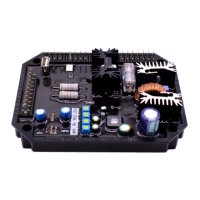
Explains the DER1's role in controlling generators, default configurations, and available versions.
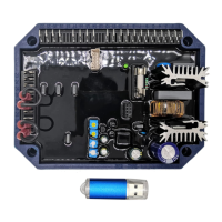
Details the USB2DxR module for parameter setting and monitoring generator operation.
Lists key technical features like DSP control, voltage supply, current limits, precision, and programmable features.
Details the terminals, names, functions, and specifications for CN1 connections.
Lists terminals, names, functions, and specifications for CN3 connections, including APO and jumpers.
Explains the purpose of VOLT, STAB, Hz, and AMP trimmers for calibration and adjustment.
Illustrates the internal connections and signal flow within the DER1 regulator.
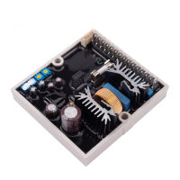
Provides overall dimensions and layout details of the DER1 regulator.
Emphasizes the importance of correct connections and checking them before power-up.
Specifies cable diameter requirements for power and signal connections.
Explains the voltage sensing scales (H and F) for different voltage ranges.
Summarizes connection configurations for various alternator voltages and sensing types.
Refers to specific drawings (SCC158/04, SCC159/04, etc.) for typical DER1 connections.
Details how to select sensing scales, use trimmers, jumpers, and software for setup.
Explains the 50/60 signal function and the APO (Active Protection Output) contact.
Describes how to remotely control output voltage using external signals or software.
Explains how to set voltage using trimmers or parameter P[19], including external control options.
Details parameters P[8] and P[9] for managing excitation current during startup to prevent overvoltage.
Describes parameter P[18] for controlling the speed of voltage reference changes.
Explains how to adjust proportional (Kp) and integral (Ki) gains using STAB trimmer or parameter P[20].
Covers the function of overcurrent protection and its calibration.
Explains how voltage regulation changes with frequency below a set threshold, signaled by alarm 6.
Details calibration procedures for underspeed protection using supervision unit or trimmer.
Describes parameter P[26] for setting the overspeed alarm intervention threshold.
Explains parameter P[14] for setting the proportional coefficient between output voltage and auxiliary voltage.
Details parameter P[24] for setting the voltage/frequency slope during startup.
Defines parameter P[25] for the operating time with a short-circuited alternator.
Covers alarm A-08 for low excitation or loss of excitation, and parameter P[27].
Lists events, their descriptions, and corresponding actions or APO output status.
Explains how alarm statuses are stored in L[38] and how indicator lights signal events.
Provides specific details for each alarm type (Over Voltage, Under Voltage, Short Circuit, etc.).
Explains how the APO output status depends on alarms and parameter P[17] settings.
Describes how to obtain the total operation time of the regulator.
Shows connection diagrams for functional checkout and parameter setting on a test bench.
Lists technical reference guides and their links for further information.
Tracks changes and updates made to the manual across different revisions.
| Brand | Mecc Alte |
|---|---|
| Model | DER1 |
| Category | Controller |
| Language | English |