DER1 digital regulator instruction manual - rev. 05 - pag. 3
The information contained in this manual may be modified without advance notice.
This revision supersedes and replaces all previous editions.
Even partial reproduction of this manual is prohibited, with any means whatsoever, without prior written
authorisation by Mecc Alte S.p.A.
INTRODUCTION
This manual contains information on the operation and use of the DER1 digital regulator.
MAIN CHARACTERISTICS
1. Architecture of the system
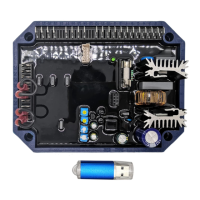
The DER1 is a voltage regulator for synchronous alternators, designed for stand alone working and
calibration; to maximize performances, the regulator should be intended as part of a system made up of at
least three components: the DER1 (control unit), a communications module (USB2DxR, for example) and
a supervision unit, as illustrated in figure 6.
The connectors for connection to and from the power generator and communications module are located
on the DER1 regulator.
The supervision unit can be made up of a personal computer, another “synoptic” device or both; it does
not have the function of controlling the system in real time, but allows programming and visualisation of all
operational parameters of the DER1.
If it is equipped with USB interface, it’s possible to use the USB2DxR communications module for its
connection.
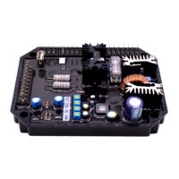
1.1 Regulator
Since the regulator is designed to control many different types of generators, it must be appropriately
configured to obtain the best performance; most of the settings are stored in a non-volatile integrated
memory (EEPROM). The first time the regulator is turned on, a default configuration will be present, which
satisfies the most widely requested characteristics and is suitable to facilitate installation: the trimmers are
active and the inputs for the external potentiometer and the 60 Hz jumper are enabled, therefore the basic
calibrations can be performed without the use of additional equipment.
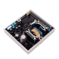
Two versions of the DER 1 and DER 1/A regulators are available; the first one is optimised for Mecc Alte
Series 3 to 38 alternators, while the second is optimised for Mecc Alte series 40, 43 and 46 alternators; the
two versions differ primarily in the default parameters.
NOTE: the parameter that defines the output voltage (with the VOLT trimmer disabled) is set on 0 (so that
the adjustment takes place on the minimum voltage).
1.2 Communications module
The USB2DxR communications module (which is provided for connection to the COM connector of the
DER1) is equipped with a USB port, through which it is possible to set the parameters (for both
configuration and operation) and “monitor” operation of the generator.
In order to avoid damage to persons and/or property, only qualified personnel, having full
knowledge and understanding of the information contained in this manual, should perform the
procedures described herein; when power to the unit is on, the voltage present may be lethal for
the operator.
All connections must be made with the power off.
The plastic protections on connectors J1 and J2 must not be removed for any reason whatsoever.