DER1 digital regulator instruction manual - rev. 05 - pag. 6
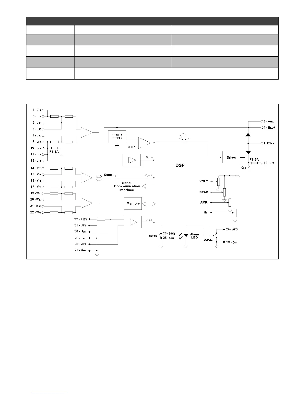
4. Block diagram
Name Function Notes
VOLT Voltage Calibration
From 75Vac to 150Vac or from 150Vac to
300Vac, see paragraph “Setting the voltage”
STAB Calibration of dynamic response
Adjustment of proportional gain, see paragraph
on “Stability”.
Hz
Calibration of underspeed protection
intervention threshold
Variation up to -20% with respect to the nominal
speed value set in parameter 50/60.
AMP
Calibration of excitation overcurrent
protection
See paragraph “Calibration of excitation
overcurrent protection”
TABELLA 3: TRIMMERS
Fig 1
INSTALLATION
Upon receipt of the digital regulator, perform a visual inspection to ensure that no damage has been
sustained during transportation and movement of the equipment. In the event of damage, advise the shipper,
the insurance company, the seller or Mecc Alte immediately. If the regulator is not installed immediately,
store it in its original packaging in a dust and humidity-free environment.
The regulator is normally installed in the generator terminal box. It is fixed with two M4x25 screws and must
be installed in a location where the temperature does not exceed the environmental conditions foreseen. The
regulator is equipped with a 5A fast-acting protection fuse. If necessary, the fuse must be replaced only wiith
a fuse of the same type and rating.