DER1 digital regulator instruction manual - rev. 05 - pag. 4
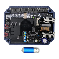
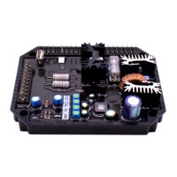
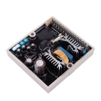
2. Technical Characteristics of the device installed on board
• Digital controlled regulator, based on DSP
• Suitable for all Mecc Alte self-regulated alternators
• Power connections through 20 poles
(1)
Fast-On connector (see fig.2)
• Protection of power winding with 5A fast acting fuse
• Signal connections (Pext, 60Hz Jumper, APO) through 10 poles mini Fast-On separate connector
• Environmental temperature: -25°C ÷ +70°C
• Voltage supply: 40Vac÷270Vac
(2)
(from auxiliary winding, output voltage or PMG)
• Maximum continuous output current: 5Adc
• Frequency range: 12Hz÷72Hz
• Three phase or single phase sensing in all connections (Y--YY-)
• Single phase or three phase sensing automatic recognition
• Average value of voltage regulation
• Voltage regulation range (sensing) from 75Vac to 300Vac
• Precision of voltage regulation: ± 1% from no-load to nominal load in static condition, with any power
factor and for frequency variations ranging from -5% to +20% of the nominal value.
• Precision of voltage regulation: ± 0,5% in stabilized conditions (load, temperature).
• Transient voltage drop and overvoltage within ± 15%
• Voltage recovery time within ± 3% of the value set, in less than 300 msec.
• Programmable Soft start
• Parameters: VOLT, STAB, AMP and Hz settable by trimmers (default), 50/60Hz settable by a
“jumper” (default), all parameters programmable via software
• 0÷2,5Vdc or -10÷+10Vdc external voltage for analogical remote control of output voltage
• Remote control of output voltage through external potentiometer (from 25Kohm to 100Kohm)
• Underspeed protection with adjustable threshold and slope
• Overvoltage and undervoltage alarms
• Excitation overcurrent protection with delayed intervention
• Underexcitation alarm/loss os excitation
(6)
• Management of temporary short circuits (start up of asynchronous motors)
• Open collector output (not insulated) signalling some allarm intervention with programmable activation in
respect of each alarm and possibility of the intervention delay and selectable active level
(6)
• Allarm conditions storage (type of alarm, number of events, duration of the last event, total time)
• Memorization of the regulator operation time
• USB communications interface (with optional USB2DxR module)
WARNING : Operation of the DER1 is not specified below 12 Hz.
NOTE (2) : with EMI external filter SDR 128/K, see Fig.4 (3m without EMI filter)
NOTE (6) : Starting from rev. 19 of the firmware