DER1 digital regulator instruction manual - rev. 05 - pag. 32
APPENDIX : DER1 SET UP ON A TEST BENCH
The operations of functional checkout and parameter setting may turn out to be easier if they are performed on a test
bench rather than with the regulator connected to the alternator.
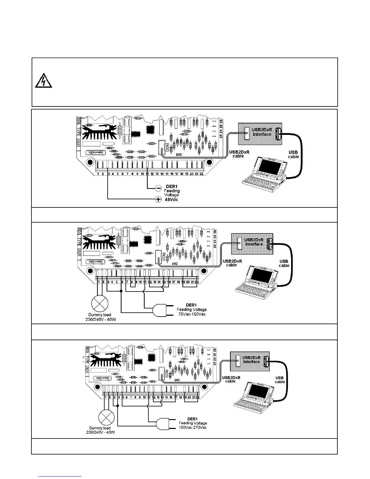
The connection diagrams of the DER1 and the USB2DxR communication interface are shown in figures 12a, 12b or 12c
based on the requested function and on the available supply voltage.
Given that some parts of the DER1 which work at high voltage are not isolated, for the safety of the operator, it
is necessary for the power source to be isolated from the electrical grid, for instance by a transformer.
The use of these types of connection is reserved to qualified personnel, able to assess the operational risks of
high voltage and who have a full knowledge of the content of this manual.
Fig. 12a: DER1 48Vdc power supply (please note that no other connections, other than the power source, are neces-
sary) for the download of the alarms without risking to modify the content of the EEPROM because of the test.
Fig. 12b: DER1 75-145Vac power supply ( Please note the sensing on terminal 7 and the jumper between terminals 6
and 3 of the DER1) for test and setup
Fig. 12c: DER1 150-270Vac power supply ( Please note the sensing on terminal 5 and the jumper between terminals 4
and 3 of the DER1) for test and setup


 To Next Page