DER2 digital regulator instruction manual - rev. 02 - pag. 17
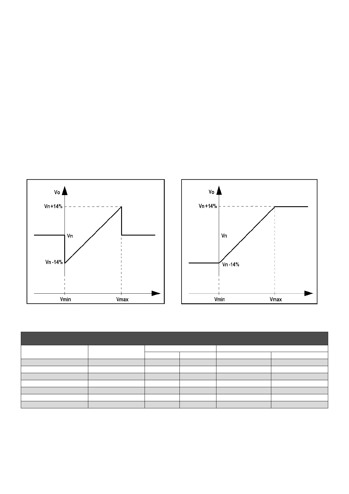
Figure 4a: without saturation of the output voltage
upon reaching the input voltage limits.
Figure 4b: with saturation of the output voltage
upon reaching the input voltage limits.
TABLE 5: HARDWARE AND SOFTWARE CONFIGURATION OF VOLTAGE REMOTE CONTROL
Input
Jumpers Flags ( configuration menu) or Parameter P[10]
JP1 (27-28) JP2 (31-32) RAM Voltage CTRL Ext. Input
Potentiometer 0Ext - Pext (29-30) Close Close Disabled (Bit B7=0) Enabled (Bit B12=1)
0V/2,5V without saturation 0Ext - Pext (29-30) Close Close Disabled (Bit B7=0) Enabled (Bit B12=1)
0V/2,5V with saturation 0Ext - Pext (29-30) Close Close Enabled (Bit B7=1) Enabled (Bit B12=1)
-10V/+10V without saturation 0Ext - ±10V (29-32) Open Open Disabled(Bit B7=0) Enabled (Bit B12=1)
-10V/+10V with saturation 0Ext - ±10V (29-32) Open Open Enabled (Bit B7=1) Enabled (Bit B12=1)
Parameter P[15] EEPROM Close Close Disabled(Bit B7=0) Disabled (Bit B12=0)
Location L[49] RAM Close Close Enabled (Bit B7=1) Disabled (Bit B12=0)
Type
With a 100Kohm linear potentiometer connected as shown in figure 4a, you have the full excursion set
with parameter P[16] (with the default value P[16]=4608 there is an excursion of ± 14%); with a 25Kohm
linear potentiometer in series with a 3.9Kohm resistor, connected as shown in figure 4b, the effect of the
external potentiometer is cut in half (with the default value P[16]=4608 there is an excursion of
approximately ± 7%).
8. Remote control of voltage
The Pext input (terminal 30) and ±10V (terminal 32) allow to obtain remote control of the output voltage by
means of a DC signal or an external potentiometer. The output voltage can be controlled by software as well
with the P[19]. The excursion range and gain of the remote control can be set independently by software
despite the output voltage control device system used (potentiometer, VDC signal or P[19]). If DC voltage is
used, it will take effect if it is within the range 0Vdc/2,5Vdc or -10Vdc/+10Vdc, when connected between
terminals 30 and 29 and subjected by jumpers JP1 and JP2; for values exceeding the aforementioned limits
(or in the event of disconnection), two options are possible: not to take the set point of external input and
return to regulation to the voltage value set with the trimmer (if enabled) or with parameter P[19], or keep the
minimum (or maximum) value of voltage that can be reached (see figures 4a and 4b). The two options can be
set with the RAM Voltage CTRL flag in the Settings/Advanced menu corresponding to the bit B7 of the
configuration word P[10] (see PARAMETERS AND OPERATIONAL DATA - Para. 2). The setting relative to
the Vext input are summarised in table 5.
NOTE: the source of DC voltage must be capable of absorbing at least 2 mA.
In making adjustments it is reccomended not to exceed the nominal value of voltage of the alternator beyond
± 10%
Relationship between analogical input and output voltage
 Loading...