DER2 digital regulator instruction manual - rev. 02 - pag. 6
3. Inputs and Outputs: technical specifications
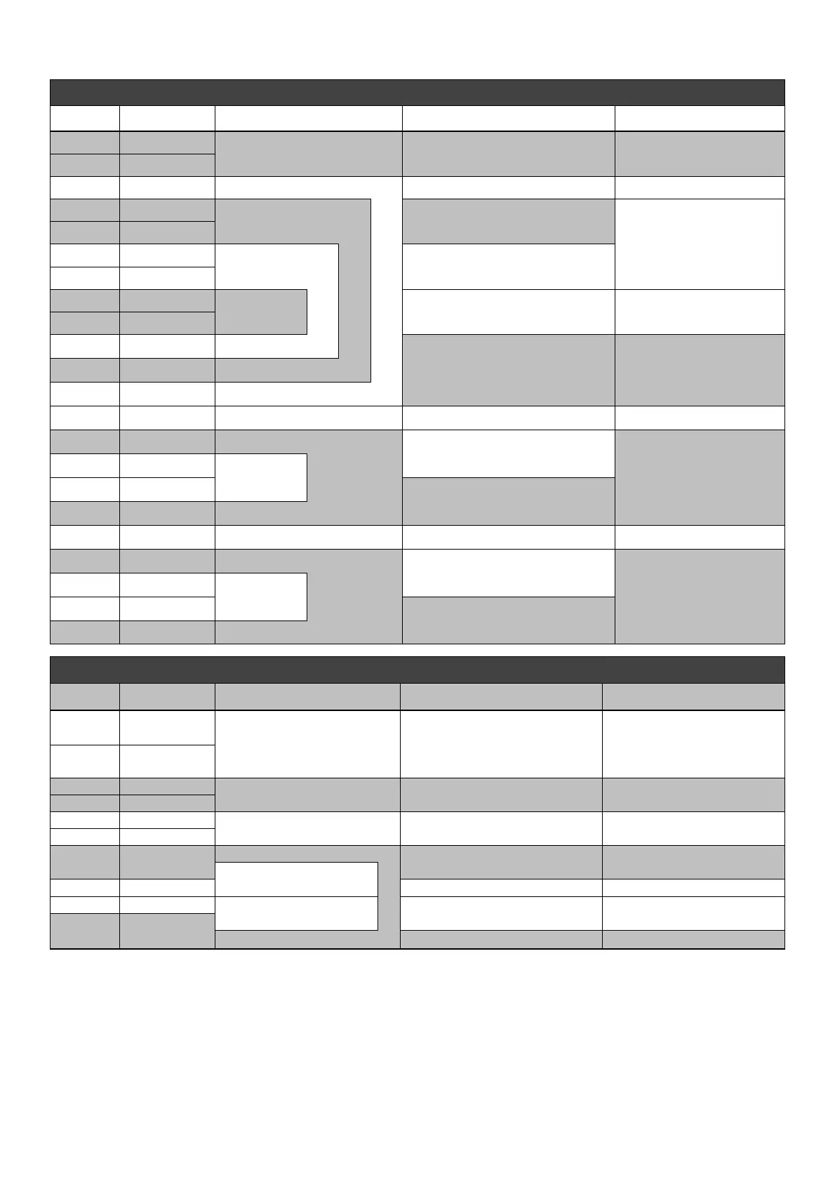
TABLE 1 : CONNECTOR CN1
Terminal
(1)
Name Function Specification Notes
1 Exc-
Excitation
Continuous Rating: 5Adc
Transitory Rating:12Adc at peak
2 Aux/Exc+
3 Aux/Exc+ Power
40÷270 Vac, Frequency: 12÷72Hz
(2)
(1)
4 UFG
Sensing
Range 2
Range 2: 150÷300 Vac
Burden: <1VA
U channel
5 UFG
6 UHG
Sensing
Range 1
Range 1: 75÷150 Vac
Burden: <1VA
7 UHG
8 UHB
Jumper
Range1
Short for sensing
75÷150 Vac
9 UFB
10 UFB
Board reference
11 UFB
12 UFB
13 -
Not present
14 VFG Sensing
Range 1: 75÷150 Vac
Burden: <1VA
V channel, to be
connected in parallel to
U channel in case of
single phase sensing
15 VHG
Sensing
Range 1
16 VHB
Scala 2: 150÷300 Vac
Burden: <1VA
17 VFB Range 2
18 -
Not present
19 WFG Sensing
Range 1: 75÷150 Vac
Burden: <1VA
W channel, unused
(with shorted inputs)
in case of single phase
sensing
20 WHG
Sensing
Range 1
21 WHB
Range 2: 150÷300 Vac
Burden: <1VA
22 WFB Range 2
Star point (12 YY or 6 Y leads
generators) is hard connected
to AVR power supply input
(1)
TABLE 2 : CONNECTOR CN3
Terminal
Name Funcion Specifications Notes
23
Common
Active
protections output
Type: Non-insulated open collector
Current: 100mA
Voltage: 30V
Max length: 30m
(3)
Programmable : active
level, activating alarm and
delay time
24
A.P.O.
25 Common
Jumper 50/60Hz
Type: Not insulated
Max length: 3m
Selection of underspeed
protection threshold
(4)
26 50/60Hz
27 0EXT
Jumper for remote voltage
control 0÷2,5Vdc
Type: Not insulated
Max length: 3m
Short for 0÷2,5Vdc input
or potentiometer
28
JP1
29
Input for remote voltage
Type: Not insulated
Max length: 30m
(3)
Regulation: ±10 %
(5)
Input for remote voltage
control 0÷2,5Vdc or Pext
30 PEXT
Input: 0÷2,5Vdc o Potentiometer 100K
Burden: 0÷1mA (sink)
31 JP2
Pext Jumper
Type: Not insulated
Max length: 3m
Short for 0÷2,5Vdc input
or potentiometer
32 ±10V
control ±10 Vdc Input: ±10Vdc
Burden: ±1mA (source/sink)
0EXT
Note 1) The terminals are connected to each other on the board: 2 with 3, 4 with 5, 6 with 7, 9 with 10, 11 and 12.
Note 2) Minimum power voltage 40 Vac at 15 Hz, 100 V at 50 Hz, 115 V at 60 Hz
Note 3) With external EMI filter 182/K (3m without EMI filter)
Note 4) 50·(100%-
αHz%) or 60·(100%-αHz%) where αHz% is the position relative to the Hz trimmer or the percen
tage value of parameter P[21]
Note 5) Value not to be exceeded. The effective range depends on parameter P[16]
 Loading...