page 37
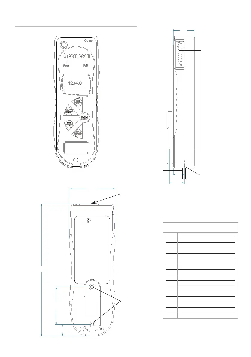
Dimensions (incl. Pin-out details)
Allocation for the pins on the
Male 15 way ‘D Type’
Communication Connector
AFG Mk 4 D Connector Pin Out:
1 Analogue Output
2 RS232 Transmit
3 RS232 Receive
4 Mitutoyo Clock Output
5 Mitutoyo Ready Output
6 + 5 Volts
7 FREEZE Reading Input
8 Stand Reverse UP
9 Footswitch 2 Input/SMART -ve out
10 Ground
11 Mitutoyo Request Input
12 Mitutoyo DATA Output
13 Footswitch 1 input
14 PLC Output
15 Stand reverse DOWN
TAPPED HOLE:
THREAD M5 x 0.8 x
5.5mm DEEP
*
* Shown with Dovetail Mounting Bracket
(supplied with Mecmesin Test Stands)
BATTERY COVER
Front View Side View
Rear View
15 WAY D-TYPE
COMMUNICATION
CONNECTOR
70
201
57
18
32
17
22.5
SMART CONNECTOR
INTERNAL
LOADCELL STUD
MALE THREAD
= 10/32UNF
(10-1000N MODELS)
= 5/16”UNC
(2500N MODEL)
EXTENSION ROD MALE THREAD
= M6 (10N - 1000N)
= 5/16”UNC (2500N)