Do you have a question about the Mecmesin AFG Series and is the answer not in the manual?
Instructions for installing and charging the device's rechargeable batteries.
Indicates the symbol and timing for low battery alerts on the gauge display.
Details on powering the gauge directly from the mains supply.
Guidance on installing standard alkaline batteries as an alternative power source.
Essential safety precautions to follow when handling and disposing of batteries.
How to attach extension rods and grips to the force gauge for testing.
Procedures for securely mounting the gauge onto a Mecmesin test stand or similar equipment.
Step-by-step instructions to turn on the force gauge and initiate its self-test sequence.
Explains how tensile and compressive forces are indicated on the gauge display with symbols.
Procedure to set the display to zero, useful for taring out weights.
How to select different units like Newtons, kgf, or lbf for force readings.
Describes how the gauge detects and stores peak tensile and compressive forces.
How to access and view the highest tensile and compressive forces recorded during a test.
Shows how the display presents both max tension and max compression readings simultaneously.
How to view only the maximum tensile force recorded during a test.
How to view only the maximum compressive force recorded during a test.
Restores the display to show running force indication without peak values.
Details on the calibrated analogue output for chart recorders and oscilloscopes.
How to transmit data to PCs, printers, or Mitutoyo devices.
Configuration parameters for PC communication, including baud rates.
Instructions to activate and use the gauge's display backlight for better visibility.
How to configure automatic power-down to conserve battery life.
How to reverse the display orientation for comfortable reading in specific applications.
Procedure to restore the gauge to its original factory settings.
Guidelines for connecting and using Mecmesin's compatible smart force and torque sensors.
How to check the loadcell status for potential overload conditions.
Explains how to access and navigate through the gauge's advanced menu system.
How to configure audible and visual alarms for pass/fail criteria or sample break.
Setting upper and lower limits for alarm triggers in tension or compression.
Selecting how alarms are indicated: audible, LED, or both.
Defining whether alarms trigger for values within or outside set limits.
Configuring conditions for a 'Pass' or 'Fail' status based on alarm triggers.
Setting the buzzer to sound continuously or in pulses for alarms.
Using alarms in conjunction with % DROP to signal sample breaks.
Illustrates various settings for alarm triggers and indicators.
Setting up the PLC signal output for automated test control.
Configuring PLC signals to trigger at specified load limits.
Tying PLC signals to the gauge's alarm settings.
Setting up signals to control Mecmesin motorised test stands.
Configuring stand functions like REVERSE, STOP, and CYCLE.
Defining conditions for stand reversal based on sample break or load limits.
Configuring test stand stop points and cycle counts for automated testing.
Setting the display to freeze upon receiving an external signal (LO or HI).
Defining the percentage drop from peak load to identify sample breaks.
How the gauge detects the force at the first sign of sample yielding or cracking.
Displaying first peak values for both tensile and compressive forces.
An example illustrating how to set and interpret the % DROP feature.
Configuring the gauge to calculate and display average load readings over time.
Choosing the gauge's throughput rate for display averaging (MED, HI, LO).
How to assign specific key functions (e.g., MAX, ZERO) to Footswitch 1.
How to assign specific key functions to Footswitch 2.
Overview of settings for interfacing with peripheral devices and internal memory storage.
Configuring communication port settings including units and baud rate.
Options for storing and sending readings to internal memory or external devices.
Setting up data transmission format, line delay, and start thresholds.
Detailed settings for transmission NULL, CR, LF, line delay, and start thresholds.
Procedures for storing, sending, and clearing data from the gauge's memory.
How to set a custom multiplier for base units, affecting displayed values.
Displays calibration codes like Tension span, Compression span, and Initial Zero.
Steps to perform a calibration check for load cell offset and overload indication.
How to adjust the display's contrast for optimal readability.
Detailed specifications for various models regarding force ranges and resolution.
Information on the gauge's accuracy, calibration, and operating temperature ranges.
Details on RS232, Mitutoyo, Analogue, and PLC signal outputs.
Electrical specifications for the PLC signal output and relay characteristics.
Information on the primary and secondary ratings of the supplied mains adaptor/charger.
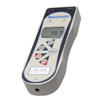
Visual representations of the gauge's physical dimensions and key features.
Detailed mapping of the 15-pin D-type communication connector pin assignments.
List of available cables and optional accessories for connecting the gauge.
Describes the capabilities of DataPlot software for logging, plotting, and analyzing force/torque data.
Overview of the MultiTest range of potentiometric and console-controlled test stands.
Highlights the Vortex-1's capabilities for computer-controlled motorised torque testing.
Listing of part numbers for various interface cables like BFG to RS232 and analogue.
| Accuracy | ±0.1% of full scale |
|---|---|
| Units of measurement | N |
| Data output | USB, RS-232 |
| Interface | USB, RS232 |
| Power | Mains power adapter or rechargeable battery |
| Dimensions | Varies by model |