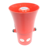
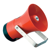
The MEDC DB3 and DB3L are a range of lightweight, all-GRP (Glass Reinforced Polyester), flameproof sounders designed for use in potentially explosive gas and dust atmospheres. They are engineered with high ingress protection to withstand harsh environmental conditions found offshore and onshore in the oil, gas, and petrochemical industries.
Function Description
The primary function of the DB3 and DB3L sounders is to provide a pre-determined audible warning sound when required by a system. They are intended for use as fire alarm devices and general warning sounders in hazardous areas. The sounders are available in various AC input voltage versions and a single DC voltage input version, with options for single or dual-tone operation.
Important Technical Specifications
Construction and Materials:
- Body and Flare: Manufactured entirely from UV stable glass reinforced polyester, ensuring corrosion resistance.
- Screws and Sinter: Stainless steel components are incorporated for enhanced durability and corrosion resistance.
- Flamepath: A tapered flamepath design is used to overcome assembly challenges associated with parallel spigot flamepaths.
- Enclosure: Glass reinforced polyester enclosures are suitable for use offshore or onshore where lightweight construction combined with corrosion resistance is required.
Electrical Specifications:
- AC Versions: Nominal operating voltage is stated on the unit label with a supply voltage tolerance of ±10%.
- DC Versions: Absolute input voltage range is 11.0Vdc to 58.0Vdc.
- Power Rating (EN54-3 Compliant): 15W.
Certification and Approvals:
- IECEx Units:
- Certified to IEC 60079-0, IEC 60079-1, and IEC 60079-7.
- Ex d IIC unit (IECEx BAS 11.0083X): Ex d IIC TG (Tamb.) Gb, Ex tb IIIC TD (Tamb.) Db IP66.
- Ex de IIC unit (IECEx BAS 11.0084X): Ex de IIC TG (Tamb.) Gb, Ex tb IIIC TD (Tamb.) Db IP66.
- Equipment Protection Level Marking: Gb (Zone 1 gas), Db (Zone 1 dust).
- ATEX Units:
- Certified to EN50014:1997, EN50018:1994, EN50019:1994, and EN50281-1-1:1998.
- EExd IIC Atex Certification Number BAS 00ATEX2097X.
- EExde IIC Atex Certification Number BAS 00ATEX2098X.
- ATEX Group and Category Marking: II 2 GD (Suitable for surface industries, Zone 1, gas, and dust).
- CE 1180 marking signifies compliance with European directives (94/9/EC).
- EN54-3 Fire Alarm Device – Sounder (11-58V DC ABSOLUTE):
- Environment Type B Outdoor applications.
- IP code (IP33C) to BS EN 60529:1992.
- CE 0832-CPR-F0566 and 1120a/01 markings.
- Electromagnetic Compatibility: BS EN 50081-1:1992 and BS EN 50081-2:1995.
Ambient Temperature Ranges and T-ratings (EN54-3 Compliant):
- DB3/DB3E:
- 15W: -20°C to +55°C (T5, T100°C)
- 15W: -20°C to +70°C (T4, T135°C)
- DB3L/DB3LE:
- 15W: -55°C to +55°C (T5, T100°C)
- 15W: -55°C to +70°C (T4, T135°C)
Sound Output (Nominal SPL @ 1M):
- Ranges from 100 dB(A) to 115 dB(A) depending on the selected tone.
- EN54-3 compliant versions have a minimum sound output of 65dB.
Functional Safety (IEC 61508):
- Safety Function: To provide a pre-described audible warning sound when required.
- Type: Type B device.
- Hardware Fault Tolerance (HFT): 0.
- Safe Failure Fraction (SFF): 74.00%.
- Proof Test Interval: 8760 hours (1 year).
- Mean Time To Repair (MTTR): 8 hours.
- Probability of Failure on Demand (PFDavg): 9.44E-03 (Low Demand Mode) – SIL 2.
- Probability of Dangerous Failure on Safety Function (PFH): 2.15E-06 (High Demand Mode) – SIL 1.
- Overall SIL-capability achieved: SIL 1 (Low Demand), SIL 1 (High Demand).
Usage Features
Mounting:
- The unit mounts via two Ø9mm mounting holes in a 'U' shaped stirrup/mounting bracket, designed to accept an M8 screw or bolt.
- A Ø13mm central hole in the mounting bracket allows for initial placement and rotation for correct orientation.
- Alignment can be adjusted by loosening two M6 screws fastening the mounting bracket to the speaker.
- The unit should be positioned to prevent dust/debris or water from settling in the re-entrant horn.
- MEDC recommends the use of stainless steel screws.
Cable Termination:
- Isolation: Power to the unit must be isolated before removing the cover assembly.
- Cover Removal:
- Exd versions: Secured with 6 off M5 cover screws (4.0mm A/F hexagon key). Twist gently clockwise and anti-clockwise while pulling away from the base.
- Exde versions: Secured with 2 off M5 cover screws (4.0mm A/F hexagon key). The cover can be lifted away.
- Fixings: Non-captive fixings should be kept in a safe, accessible location.
- Glands and Stopping Plugs: Only correct listed or certified cable glands and stopping plugs should be used to maintain NEMA/IP rating. MEDC recommends HYLOMAR PL32 sealing compound on threads.
- Earthing: The internal earth terminal (where fitted) must be used for equipment grounding.
- Wiring: Cable termination should adhere to application specifications. All cables and cores should be correctly identified. Refer to the provided wiring diagram.
- Cover Replacement: Carefully replace the cover assembly, avoiding damage to mating surfaces. Tighten cover screws evenly. Ensure the O-ring is seated correctly. For Exd certified versions, maintain a maximum gap of 0.15mm between cover and base.
Wiring Options (6 basic configurations):
- Types 1 & 2 (DC Input, Single Tone): 6 terminals (T1-T6). Supply: T1 (+ve), T3 (-ve). Loop out: T4 & T6.
- Types 3 & 4 (DC Input, Dual Tone): 6 terminals (T1-T6).
- 2-wire system: Supply: T1 (+ve), T2 (-ve) for Tone 1; T1 (-ve), T2 (+ve) for Tone 2. Loop out: T4 & T5. Optional EOL resistor on T4, T5.
- 3-wire system: Supply: T1 (common +ve), T2 (-ve 1) for Tone 1; T1 (common +ve), T3 (-ve 2) for Tone 2. Loop out: T4, T5 & T6. Optional EOL resistor on T4, T5 or T4, T6.
- Type 5 (AC Input, Single Tone): 4 terminals (L, L, N, N). Supply: one L,N pair. Loop out: second L,N pair.
- Type 6 (AC Input, Single Tone): 6 terminals (T1-T6). Supply: T1 (L), T2 (N). Loop out: T4 & T5.
Tone Selection:
- A 5-way DIL switch selects the required tone from 32 options, including various alternating, sweeping, continuous, and intermittent tones.
- Special tones can be requested at the time of ordering, with a separate tones list provided.
- EN54-3 compliant tones are marked with an asterisk in the tone table.
Volume Control:
- Fitted adjacent to DIL switches on DC units and on the transformer on AC units.
- Maximum volume is achieved when turned fully clockwise.
- Minimum volume is achieved when turned fully anticlockwise.
- WARNING: Do not attempt to turn the volume control past its limits of movement to avoid damage.
Special Conditions for Safe Use (IECEx/ATEX):
- Not suitable for use in atmospheres containing carbon disulphide.
- For Exe versions:
- Only one single or multiple strand wiring lead per terminal, unless multiple conductors are joined in a suitable insulated boot lace ferrule.
- Leads to terminals must be insulated for at least 275V, extending to within 1mm of the terminal throat metal.
- All terminal screws (used and unused) must be fully tightened.
- Minimum creepage and clearance distances between terminals and adjacent conductive parts (including cable entry devices) must be at least 5mm.
- Dust Atmospheres: Flameproof cable entry devices or stopping plugs must maintain IP6X integrity.
- Painting and surface finishes, other than those applied by the manufacturer, are not permitted.
Maintenance Features
General Maintenance:
- The unit requires little or no maintenance during its working life.
- GRP construction resists attack by most acids, alkalis, and chemicals, comparable to most metal products.
- Visual inspection is recommended if abnormal or unusual environmental conditions (e.g., plant damage, accident) occur.
Cleaning:
- Clean the exterior only with a damp cloth to avoid electrostatic charge build-up.
Repairs and Spares:
- Repairs should be undertaken by returning the unit to MEDC or by an authorized repairer of Ex equipment.
- All parts of the unit are replaceable.
- If a significant quantity of units is acquired, it is recommended to make spares available. Contact MEDC Technical Sales Engineers for requirements.
Functional Safety Maintenance:
- The unit should be tested at regular intervals to identify any malfunctions, in accordance with the safety manual.
- All information associated with field failures of this product should be collected under a dependability management process (e.g., IEC 60300-3-2) and reported to the manufacturer.
- The user must comply with manufacturer's user documentation (Safety Manual and Technical Manual) regarding functional safety aspects, including application, installation, operation, maintenance, proof tests, maximum ratings, environmental conditions, and repair.
- Selection, installation, configuration, overall validation, maintenance, and repair of the equipment for safety functions must be carried out by competent personnel, adhering to manufacturer's conditions and recommendations.