MediaStar 782-DS Digital Media Player
Installation
This LAN-Caster unit should only be used in a MediaStar Evolution 770 rack that has been fully installed in accordance
with its safety instructions. Refer to the ‘Connecting Terrestrial RF’ section for recommendations of the antenna
Lightening protection required for this equipment. There are no user serviceable parts within this module. Refer all
servicing to qualied service personnel.
The 783 LAN-Caster module may be installed in the 770 rack with the power on or o. If the rack is powered, take
care to ensure this module is engaged correctly in the plastic card guides and does not touch adjacent cards as it is
slid into (or pulled out of) the rack. If the 770 rack is powered down to install a new module, please remember that
all video/audio services being provided by the equipment in that rack will be lost while it is powered o. Electrical
static discharge precautions should be taken when handling the module. If you wish to use a CAM module with the
LAN-Caster, this should be installed inside the module before it is inserted in the rack. Please see the CAM installation
instructions later in this guide for further details.
Quick Start Guide
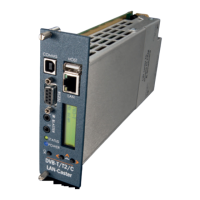
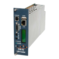
783 DVB Lan-Caster Unit
200-2342_v2
2/12
To install the 783 module, do the following:
1. Remove the existing front panel blanking plate(s) on
the770 rack. This is done by unscrewing the nger-screw
fasteners. Retain this blanking plate in case the LAN-
Caster module is removed from the rack in the future.
2. Carefully locate the top and bottom edges of the blade’s
printed circuit board (PCB) into the plastic rack slides, and
gently push it in. As the ‘blade’ reaches the back of the
rack, a plastic aperture cover on the rear of the rack will
be pushed o by the module’s connectors. Collect the
discarded aperture cover and dispose of it correctly.
If the rack is powered up, the new module will automat-
ically power up as it is pushed in and the BLUE POWER
LED on the front of the LAN-Caster will be on. The LCD
panel will show the boot up progress of the unit, then
its operational status.
3. Tighten the top and bottom nger screw fasteners to
hold the module in the rack
4. Connect the RF input cable to the rear of the
LAN-Caster in accordance with the instructions below.
5. Set the unit’s IP address, in accordance with the
instructions shown below. Only use IP address details
that have been supplied by your network administrator.
6. Plug the LAN-Caster into the LAN switch using the CAT5
patch cable supplied. It will Auto-negotiate a 100Mbps
link with your network switch.
7. Connect to the LAN-Caster’s conguration web pages
using a PC and Web browser software (e.g. Internet
Explorer, Chrome or Firefox), by entering the LAN-Caster’s
IP address into the browser’s address bar. The LAN-Cast-
er’s specication page will then be shown.
8. Click on the Installation page link on the left hand side
panel, and select appropriate DVB Mode – DVB-T or
DVB-C. Once selected you can click on the Channel Setup
page and click the SCAN button. This will initiate an RF
frequency scan with a progress bar showing the scan
progress. When the scan is complete, a list of detected
RF multiplexes will be shown.
9. Click on the RF multiplex ‘radio’ button to show a list
of the TV and Radio channels that are available from a
particular multiplex at the bottom of the web page. Select
the channels to stream on the network, by ticking the
‘Enabled’ tick-box and entering the stream details into
the webpage. Upto 15 channels may be simultaneously
transmitted, each on its own multicast or unicast address.
Press the APPLY button at the bottom of the page to save
these settings and start the stream transmission on the
network. The channel stream parameters include the
multicast (or unicast) stream address, portnumber, TTL,
and the Dierentiated Services Code Point (DSCP for QoS
packet tagging). Consult your network administrator to
get suitable values for these settings.
Channel settings may be stored for more than one RF
multiplex at a time, but only the channels on the currently
TUNED multiplex will be streamed on the network. The
rotating ‘Tuned’ icon on the list of multiplexes shows
which multiplex is currently ‘Tuned’. When a non ‘Tuned’
multiplex is selected, a tick-box will appear at the bottom
of the webpage to allow this RF multiplex to be ‘Tuned’.
If you don’t know the RF multiplex that contains your
desired TV channel, click on the Channel List link on the left
hand side and click on the letter of the channel name you
wish to stream. An alphabetical list of the channels starting
with the specied rst letter will be shown. Click on the
name of the channel you wish to stream – this will then take
you back to the Channel Setup page with the appropriate
RF multiplex selected. Scroll to the bottom of the page to
see all the channels available from that multiplex.
10.
In ‘normal’ operation when the RF feed is present and the
LAN-Caster is streaming onto the network, the STATUS LED
on the front panel will be constant GREEN. If the RF feed is
missing or the streams have been turned o, the STATUS
LED will ash GREEN. The LCD will show the‘normal’
operating status or the highest priority error condition.
During boot, the STATUS LED will ash ORANGE. If the
STATUS LED is ashing RED, a softwareupgrade is in
progress, and if the STATUS LED shows constant RED,
and internal error has occurred and the unit should be
returned to Cabletime for repair.
 Loading...