about 5 years; less if subjected to high temperatures for much
of the working day. To reduce the chances of sudden failure,
two batteries are used, operating in parallel. If either battery
fails, the instrument will continue to operate on the good battery
but the ‘FS2’ indication will flash constantly. (See ‘Condition
and Warning Indicators’).
Charging the batteries should be done in a dry environment
(the instrument is not waterproof with the charging cover open).
Unplug the test leads and slide the charging cover open. (This
operation renders the test lead sockets inaccessible and
therefore prevents any danger of having the test leads
connected to dangerous voltages). Connecting a.c. (50/60 Hz)
voltages (95 V to 265 V) to the IEC socket will commence
charging, which is indicated by the red lamp. An overnight
charge will normally be sufficient. Turning the instrument on will
show the state of charge.
It is possible to charge the batteries from a 12 to 15 V d.c.
supply using the round socket. However, this is slow and
unlikely to provide a full charge. Applying more than 15 V is
likely to overcharge the batteries.
Battery Charging Notes
1) Do not leave batteries in a totally discharged state
2) If instrument is not used, recharge the batteries for at least
24 hours every 6 months. (More frequently if the storage
temperature is >40 °C).
3) 16 hours charging (from a fully discharged state) will
achieve at least 90% of a full charge. It is beneficial to
continue charging for several days and no harm will be
done if the charger is left on indefinitely.
4) The battery should only be charged at temperatures in the
range 0 °C to 40°C.
GUARD TERMINAL
The guard terminal is at the same voltage as the negative
terminal. A fuse (FS2) protects the low impedance guard circuit
from the application of external voltage. Guard fuse failure will
be indicated on the display only when the guard circuit is in
use. To check whether the fuse has blown, connect the positive
terminal to the guard terminal and start a 500 V test. If the
display flag flashes by ‘FS2’ the fuse has blown (see
‘Condition and Warning Indicators‘). FS2 is located in the
charger recess.
Using The Guard Terminal
For basic insulation tests the guard terminal will not be used.
Most insulation tests can be performed by connecting the
specimen between the ‘+’ and ‘–’ terminals. These tests will
show up any deficiencies in the insulation, whether they are
caused by leakage through the insulator body or across its
surface.
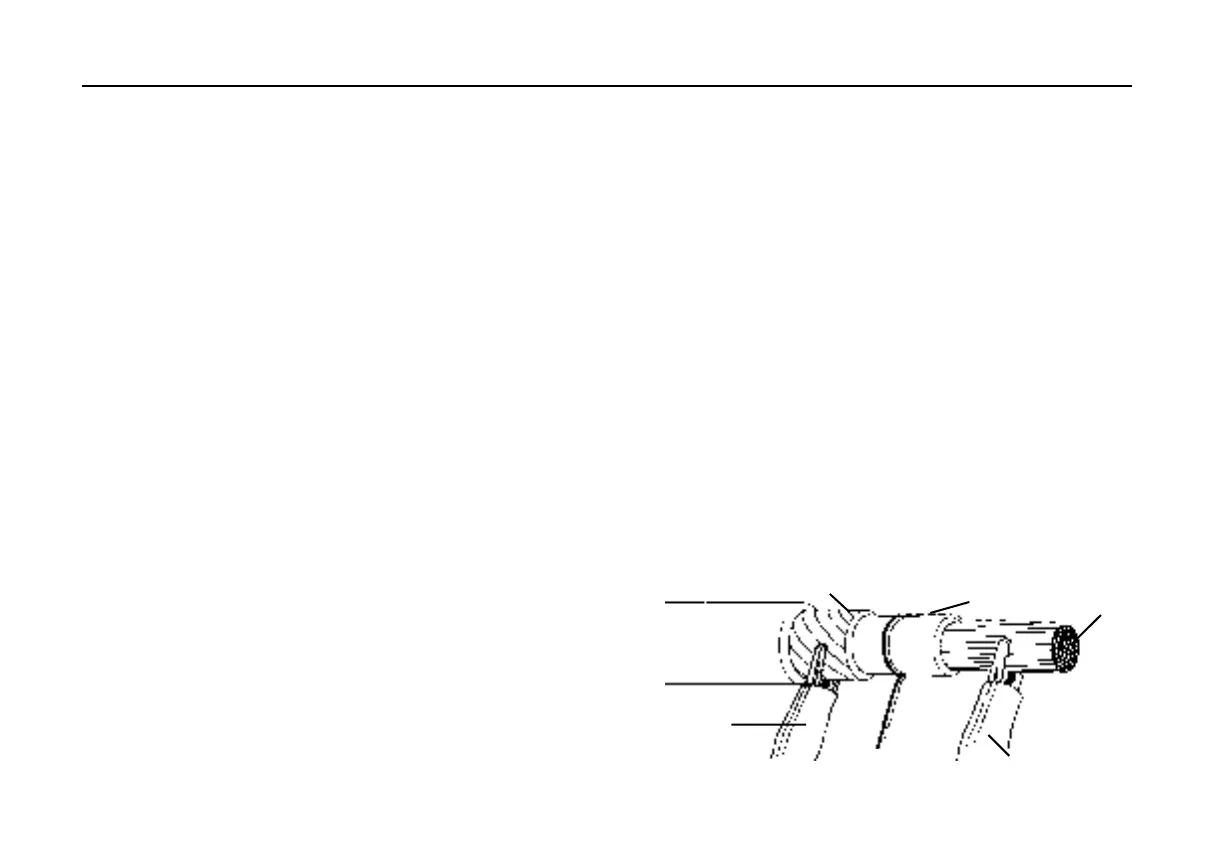
To distinguish between body leakage and surface leakage the
guard terminal ‘G’ may be used. In this way surface leakage
current is removed before it enters the measurement circuit via
the ‘–’ terminal.
10
to ‘G’ terminal
to ‘+’ terminal
Cable Core
Leakage path
Outer Sheath
to ‘-’ terminal
Covering