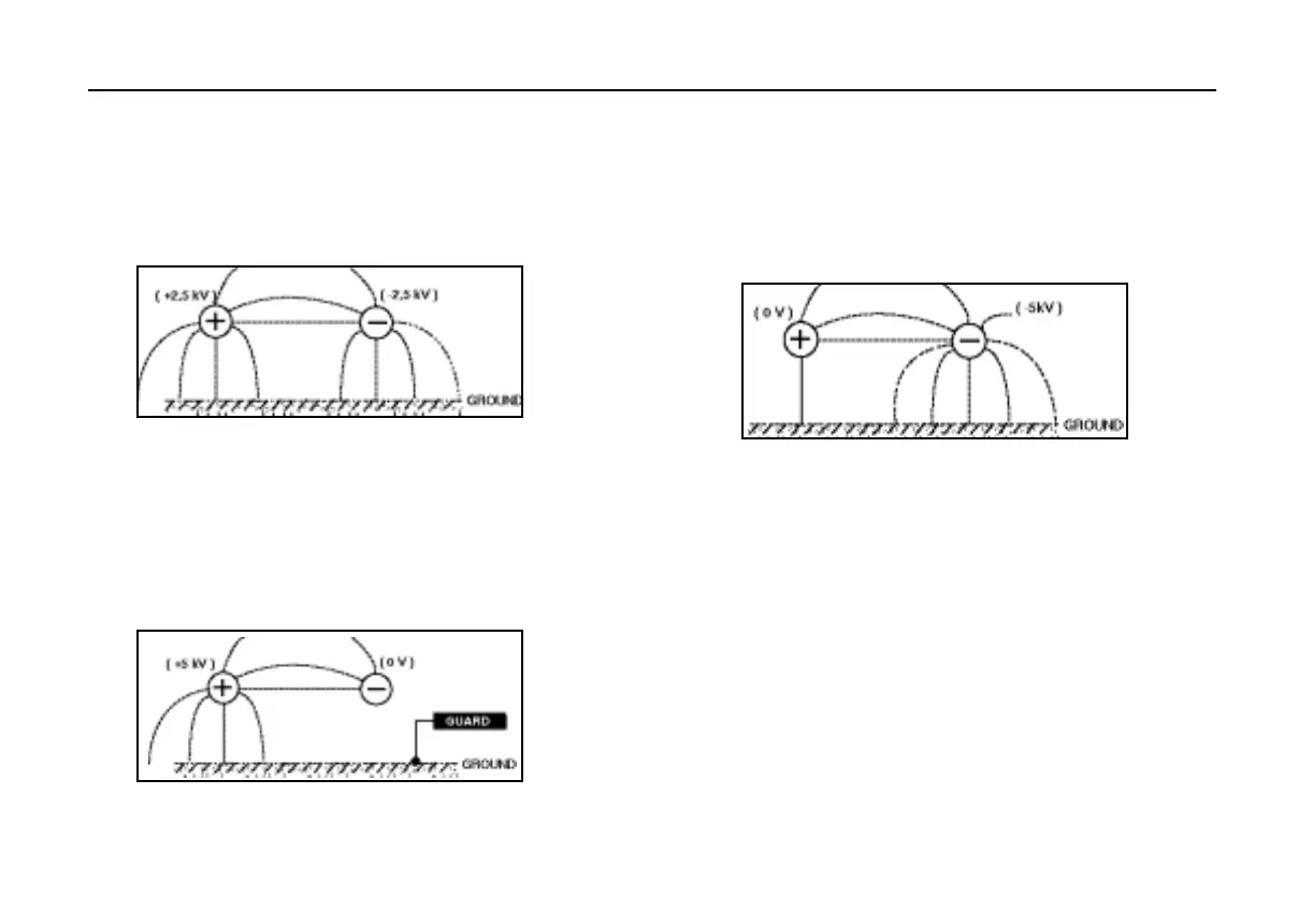
Figure 3. shows a problem which can occur. If one end of the
sample is grounded and this is required to be connected to the
positive terminal, then the negative (measurement) lead is
surrounded by a 5 kV field. This is likely to cause at least 1 nA of
unwanted leakage current, representing a 5 TΩ resistance in
parallel with the sample under test.
Figure 3.
When taking measurements above 100 GΩ therefore, the user
should where possible ground the Guard Lead as shown in
figure 2, otherwise parallel leakage paths may occur.
Stress Considerations
Measurement above 100 GΩ
Figure 1. shows the stresses and subsequent leakages
which will occur between the test leads if neither is
connected to earth (ground). These leakages have
significant effect and occur through the air itself.
Figure 1.
Figure 2. shows the effect of connecting the guard lead to
the ground. This reduces the stray leakage into the negative
(measurement input) terminal considerably, but this
technique is only permissible if the item under test is
isolated from the ground. (‘Isolated’ means insulated by a
resistance of at least 5 MΩ for the positive terminal or 10 kΩ
for the negative terminal).
Figure 2.
16