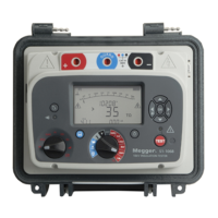
The Megger S1-5010 is an advanced diagnostic insulation tester designed for various electrical equipment, offering measurement capabilities up to several Teraohms (TΩ). It performs automatic tests, ensuring consistent operation without operator input, and can store results internally or be operated from a PC. Its flexible power supply options and robust, portable construction make it suitable for a wide range of applications, particularly for analyzing insulation in large machines, HV generators, and cables.
Function Description
The S1-5010 measures insulation resistance continuously at selected voltages. It can perform Polarization Index (PI) and Dielectric Discharge (DD) tests automatically, with adjustable test durations and voltages. A Step Voltage test can also be performed automatically at 2500 V or 5000 V with a fixed duration of 5 minutes. The instrument can be configured to restrict operation to user-defined voltages, disable graph plotting, or disable specific test types via the 'Setup' screen, which can be protected by a security code.
The device features a switchable filtering system to ensure stable readings even in the presence of high levels of 50 Hz or 60 Hz interference. When turned on, voltages exceeding 50 volts across the + and - terminals are indicated on the display with flashing HV symbols. Capacitive loads are automatically discharged at the end of a test.
Important Technical Specifications
- Test Voltages: 500 V, 1000 V, 2500 V, 5000 V, and 25 V to 5000 V in 25 V steps.
- Test Voltage Accuracy: ±5% on 10 MΩ load and above; ±25 V at test voltage <500 V; ±12 V at test voltage <125 V.
- Test Current Limit: 2 mA or 5 mA (selectable).
- Charge Time: <2.5 seconds per µF to charge to 5 kV at 5 mA.
- Measurement Ranges (Digital):
- 10 kΩ to 500 GΩ at 500 V
- 10 kΩ to 1 TΩ at 1000 V
- 10 kΩ to 2.5 TΩ at 2500 V
- 10 kΩ to 5 TΩ at 5000 V
- Measurement Ranges (Analogue):
- Voltage: 50 to 1000 V a.c./d.c. (5000 V when testing)
- Current: 0.01 nA to 999 µA
- Capacitance: 0.01 µF - 10.0 µF (measures up to 20 µF if <2.5 kV)
- Resistance: 10 kΩ to 1 TΩ
- Accuracy (0-30°C):
- Resistance: ±5% 1 MΩ to 1 TΩ at 5 kV; ±5% 1 MΩ to 100 GΩ at 500 V; ±5% 1 MΩ to 10 GΩ at 50 V; ±20% 100 kΩ to 1 MΩ and 1 TΩ to 5 TΩ at 5 kV; ±20% 100 kΩ to 1 MΩ and 100 GΩ to 500 GΩ at 500 V.
- d.c. Test Voltage: ±2% ±1 V
- Current: ±5% ±0.2 nA
- Capacitance: ±5% ±0.01 µF
- Interference Rejection: 4 mA at 50/60 Hz for <5% additional error (for test volts ≥ 500 V).
- Max Capacitance Discharge: 20.0 µF at 5 kV, or 80 µF at 2.5 kV.
- Discharge Time: <100 ms per µF from 5 kV to 50 V.
- Guard Terminal: Guards out parallel resistance down to 250 kΩ. Maximum additional error 5% at 100 MΩ.
- Operational Supply: 95-280 V a.c. / 12-15 V a.c. or d.c.
- Test Duration: 15 seconds to 90 minutes.
- Battery: Internal rechargeable 12 V, 7 Ah lead acid.
- Battery Life: At least 8 hours from a fully charged battery.
- Display: Backlit dot matrix LCD (256 x 128 pixels), bargraph style level indicator.
- Safety: Conforms to IEC 61010-1 Voltmeter rated for use on 300 V phase to earth systems, Category III.
- Environmental Protection: IP54 with side recess panel closed.
- EMC: In accordance with IEC61326-1.
- Temperature Range: Operating -20°C to +50°C; Storage -25°C to +65°C.
- Maximum Altitude: 2000 m.
- Humidity Range: 90% RH non-condensing at 40°C.
- Weight: 9 kg.
- Dimensions: 327 mm x 316 mm x 196 mm (+ 60 mm pouch).
Usage Features
- Power Supply: Can be powered from the main supply (95-280V~) or its internal rechargeable battery, providing at least 8 hours of continuous testing. The battery symbol on the display indicates capacity. Connecting to either the main supply or the 12V connector in the side recess panel automatically charges the battery, whether the instrument is on or off.
- User Interface: Features a display with four tactile keys for controlling the electrical 'noise' filter, contrast, and back-light. Left and right-hand cursor keys are used for navigation and selection.
- Test Modes: Supports Insulation Resistance Testing, Polarization Index Testing, Dielectric Discharge Testing, Step Voltage Testing, and Fault Conditioning (Burn) mode.
- Setup Procedures: Allows users to configure language, test parameters (IR, SV, DD, PI), enable/disable test modes, delete stored results, set date/time, printer/PC baud rates, 'Power On' and 'Setup' security codes, date format, current limit, data output rate, and the locking test button.
- Starting/Stopping Tests: Tests are initiated by pressing the red test button for at least one second. Warning symbols and flashing indicators signal a test in progress. Tests can be stopped manually by pressing the red button again or will terminate automatically after the set duration, excessive electrical noise, circuit breakdown, battery exhaustion, or guard fuse rupture.
- Filter System: Offers various filter settings (No Filter, FILT 3, FILT 10, FILT 30, FILT 100) to optimize settling time and reject AC interference.
- Fault Conditioning (Burn) Mode: Disables normal breakdown detection, allowing the insulation test voltage to continue even after a breakdown to help locate the failure point. Requires the test button to be set to 'LOCKED'.
- Data Storage and Retrieval: Automatically stores test results (up to 75 tests) when a test runs for more than one minute, identified by date and test number. Older results are erased if storage capacity is exceeded. Results can be displayed on the instrument, downloaded to a printer, or downloaded to a PC in 'Real Time' or 'Batch' mode via the RS232 connection.
- Remote Operation: Can be controlled directly from a PC using the S1-S1 software package, allowing for automated test sequences.
- Safety Features: Double insulated plastic case, double insulated test lead connectors, one-second delayed start test button, high voltage warning symbols (flashing on display and test terminal light), and a 5V logic signal output for an external warning light.
Maintenance Features
- Preventive Maintenance: Regular insulation testing helps detect deteriorating insulation. The S1-5010 supports this by storing results for trend analysis.
- Calibration Check: The instrument performs an automatic calibration check upon power-on to ensure the measurement system is working correctly. Users can perform additional checks by running insulation tests with disconnected leads or at various voltages to verify voltmeter accuracy.
- Fuse Replacement: Replacement fuses must be of the correct type and rating (200 mA - 250 V).
- Cleaning: The instrument should be wiped with a clean cloth dampened with soapy water or Isopropyl alcohol (IPA) when disconnected.
- Battery Management: An internal battery management system switches the instrument off after ten minutes of inactivity to conserve power. Test results and settings are protected by a backup battery.
- Repair and Warranty: New instruments are guaranteed for 1 year from the date of purchase. Repairs should be handled by suitably trained and qualified personnel or approved repair companies. Megger provides repair services and genuine spare parts.