Do you have a question about the Megger SVERKER 650 and is the answer not in the manual?
Explanation of warning symbols and protective conductor terminal used in the manual.
Essential safety guidelines and precautions for operating the instrument safely.
Key considerations and safety guidelines before operating the SVERKER 650.
Step-by-step procedure for testing current relays using the instrument.
Procedure for connecting and testing voltage relays with the SVERKER 650.
Guidance on testing power relays, including current coil and voltage coil connections.
How to connect the circuit and use the timer for time measurements.
Procedure for measuring time response for over-current and over-voltage relays.
Steps for measuring time response for under-current and under-voltage relays.
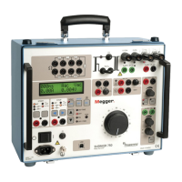
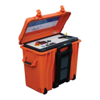
The SVERKER 650 is a robust and versatile relay test unit designed for comprehensive testing of various types of relays, including current, voltage, and power relays. This instrument is engineered to provide reliable performance in high-voltage substations and industrial environments, making it an essential tool for ensuring the proper functioning of protective relay systems. Its user-friendly design, coupled with a range of safety features, makes it suitable for both experienced technicians and those new to relay testing.
The primary function of the SVERKER 650 is to simulate fault conditions and measure the response time of protective relays. It generates controlled current and voltage outputs to trigger the relays and precisely records the time it takes for them to operate. This capability is crucial for verifying the accuracy and reliability of relay settings, which are vital for the protection of electrical grids and industrial equipment.
The unit is equipped with multiple output terminals for current and voltage, allowing it to test a wide array of relay types. For current relays, it can provide outputs in ranges such as 0-10 A, 0-40 A, and 0-100 A. For voltage relays, it offers outputs up to 250 V AC and 350 V DC. This flexibility ensures that the SVERKER 650 can cater to different relay specifications and testing requirements.
A key feature of the SVERKER 650 is its built-in electric timer, which is independent of the mains frequency. This timer measures the relay operating time with high accuracy, down to milliseconds, providing precise data for analysis. The timer can be started internally by the unit's output or externally via a dedicated terminal, offering versatility in test setup.
For testing power relays, the SVERKER 650 can simulate both current and voltage conditions. It includes a built-in 10 µF capacitor that provides a 90° phase shift, which is essential for testing reactive relays. This allows technicians to accurately assess the performance of relays that respond to both magnitude and phase relationships of current and voltage.
The instrument also incorporates a set of resistors that can be used as a voltage divider, further enhancing its capability to test various voltage relay configurations. This allows for fine-tuning of the voltage signals to match specific relay operating points.
Operating the SVERKER 650 is designed to be straightforward, with clear instructions provided for each type of relay test. Before any operation, users are advised to set the variable transformer to the "0" position to ensure a safe starting point.
For current relay testing, the process involves connecting the circuit to the appropriate output terminals, increasing the current to the operating value using the variable transformer, and monitoring the current on the built-in ammeter or an external instrument for better accuracy. The unit emphasizes the importance of short-circuiting the current transformer terminal when current is flowing, either through a short-circuit clamp or an external ammeter, to prevent damage and ensure safety.
Voltage relay testing follows a similar procedure, where the circuit is connected to the voltage output terminals, and the voltage is increased to the operating value. The SVERKER 650 can also connect its 0-250 V terminals in series with mains output terminals for higher AC voltage requirements, or use its 0-350 V DC terminals for DC voltage relays.
When testing power relays, both current and voltage coils are connected. The current coil is typically connected in series with the built-in capacitor for reactive relays, while the voltage coil is connected to the 110 V CA terminals or across the resistor set. The current is then increased to the operating value, and both current and voltage are monitored. The manual notes that polarity might need to be shifted if the relay function fails to appear, indicating the importance of understanding relay characteristics.
Time measurement is an integral part of relay testing. The SVERKER 650's timer can be connected to potential-free terminals or DC voltage 3-350 V. The timer stops when the circuit is broken, and a yellow signal lamp illuminates. For continuous measurements, the main switch must be reset to "OFF" before restarting. The timer can also be started externally, providing flexibility for complex test setups.
The instrument features a main switch (S1) for overall power control, an on/off switch (S2) for specific terminals (U6 and U7), a selector voltage range switch (S3) for terminal U6, and a make/break switch (S4) for the timer. A voltage adjustment terminal (R5) allows for precise control of the output voltage. These controls are intuitively placed on the control panel, making operation efficient.
The SVERKER 650 is built as a rugged instrument, but proper handling and maintenance are crucial for its longevity and reliable operation. The manual provides clear safety instructions, emphasizing the importance of reading and complying with them, as well as adhering to local safety regulations.
One critical safety instruction is to always turn off the equipment before connecting any leads. This prevents accidental shocks and damage to the instrument or the relay under test. The use of safety connecting leads is also mandated to ensure secure and safe connections.
The instrument is electrically fully isolated in all measuring ranges, except for the mains output, which enhances user safety. The output transformer is protected by a thermal contact, which automatically resets when the temperature drops, preventing overheating and potential damage. Additionally, the U6 output has over-current protection that breaks the circuit in case of overload, resetting after approximately 30 seconds when S2 is switched off.
For cleaning, users are instructed to disconnect the instrument from the mains supply and use a damp cloth, avoiding liquid or aerosol cleaners. This prevents moisture ingress and damage to internal components.
The manual strongly advises against attempting to service the instrument oneself, as opening covers may expose users to dangerous voltages and will void the warranty. All servicing should be referred to Megger authorized personnel. If the instrument needs to be returned for service, it should be packed in its original crate or one of equivalent strength to prevent damage during transit.
The SVERKER 650 also features a protective conductor terminal, indicating the importance of connecting protective earth (ground) during operation. This is a fundamental safety measure to protect against electrical hazards.
The instrument is designed to be robust against non-linear impedance relays, which can cause current distortion. This can be mitigated by connecting a resistance in series with the primary winding of the output transformer, demonstrating a design consideration for practical field conditions.
Overall, the SVERKER 650 is a comprehensive and safe relay test unit, designed for reliable performance and ease of use in demanding electrical testing environments, with clear guidelines for both operation and maintenance to ensure user safety and instrument longevity.
| Display | LCD |
|---|---|
| Power Supply | 100 - 240 V AC, 50/60 Hz |
| Voltage Output Range | 0-300 V |
| Current Output Range | 0 to 20 A |
| Phase Angle Adjustment | 0 - 360 degrees |