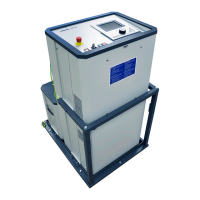
The Megger SPG 40 is an operating manual for a Test and Fault Locating System, specifically the SPG 40 model. This document, identified as Issue 9 (01/2017) – EN 128312675, provides comprehensive information about the device, its functions, technical specifications, usage, and maintenance.
Function Description
The SPG 40 is designed for fault locating in low and medium voltage networks. Its primary functions include:
- DC-Testing: Performing DC tests on cables.
- Breakdown recognition: Identifying and recognizing cable breakdowns.
- Measuring leakage resistance: Quantifying the leakage resistance of cables.
- ARM filter for prelocating methods (TDR (optional), Decay, ICE, ICE-Plus): Utilizing various prelocating methods with an Arc Reflection Method (ARM) filter to determine the approximate location of faults.
- Further prelocating methods (Decay, ICE, ICE-Plus): Employing additional prelocating techniques for fault localization.
- Pinpoint locating with step voltage or acoustic method: Precisely locating faults using either the step voltage method or an acoustic method.
- Burning: A method used to reduce fault resistance to a level suitable for other fault locating techniques.
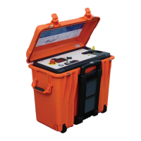
The system can be used as a stand-alone unit or as part of a combined fault locating system, such as the Surgeflex 40 (SFX 40), which enhances its capabilities with a reflectometer like the Teleflex SX or T3060. When combined with a reflectometer, the SPG 40 is suitable for direct control of the SPG 40. This integration allows for a fully fledged fault locating system, potentially including a separate SPG 40 in a test van (Compact City) with necessary HV operating elements (Teleflex SX-M) and remote control.
Important Technical Specifications
The SPG 40 offers a range of technical specifications that highlight its capabilities:
- Display: ¼ VGA display for status, input, help, and results, featuring a "single-button-operation" interface.
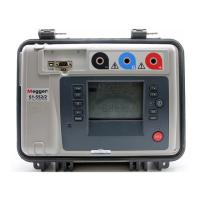
- Insulation Test:
- Voltages: 500 ... 5000 V, in steps of 500 V.
- Ranges: 1 kΩ, 1 MΩ, 100 MΩ.
- DC Testing: 0 ... 40 kV DC.
- Leakage current display: 0 ... 1/10 mA auto-ranging, 0 ... 100 mA during changing phase.
- Breakdown recognition: 0 ... 40 kV.
- Burning:
- Voltage: 0 ... 8 kV; 0 ... 20 kV.
- Current: 700 mA; 100 mA.
- Surge generator (SPG 40-25): 0 ... 12.5 kV and 0 ... 25 kV.
- Surge generator (SPG 40-32): 0 ... 16 kV and 0 ... 32 kV.
- Surge generator - options:
- 0 ... 4 kV, 0 ... 8 kV or 0 ... 4/8 kV.
- 0 ... 3 kV, 0 ... 6 kV or 0 ... 3/6 kV.
- Surge energy: max. 1000 Joules in each range (optional: 2000 Joules).
- Surge rate: 3 ... 10 sec. and single pulse.
- Sheath fault location: 0 ... 5 kV, 5 ... 10 kV.
- Adjustable current output.
- Pulse ratio: continuous, 1:3; 1:4; 1:6 (sec).
- HV-Fault Prelocation (with optional TDR):
- ARM (integrated filter).
- Impulse Current (integrated coupler).
- Decay (integrated coupler).
- ICE-Plus.
- Operating temp.: -10 ... + 50 °C.
- Mains supply: 230 VAC ±10% (optional: 115 VAC ±10%); 50 / 60 Hz (Sinus).
- Power input: 1.7 kVA max.
- AC mains fuses: 2 x T 8 A (for 230 V), 2 x T 16 A (for 115 V).
- Protection category: IP20 (according to EN 60529).
- Dimensions: 545 x 430 x 1050 mm (L x W x H).
- Weight: approx. 116 kg.
Usage Features
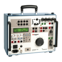
The SPG 40 is designed for ease of use with its "easy GO" operation, featuring just one rotary selector. The high voltage setting can be activated with a separate hardware button. The operating panel is located at the top of the SPG 40, with an external control unit optionally available.
Key operational aspects include:
- Safety Advice: The manual emphasizes safety, outlining general advice, electrical advice, and specific warnings regarding high voltage. It stresses the importance of trained personnel, proper earthing, and adherence to safety regulations (VDE 0104, EN 50191).
- Controls: The device features an emergency OFF button, push-buttons for on/off switch, key switch, HV-ON, and HV-OFF, a rotary selector, and a display.
- Electrical Connection: Detailed instructions are provided for connecting the earthing cable, FU cable (auxiliary earth), test object, mains, and external safety device.
- Safety Earth: The SPG 40 requires a good safety earth connection (e.g., station earth) to protect against dangerous voltages.
- Auxiliary Earth / FU-Safety Circuit: The FU-safety circuit ensures that the unit and surrounding cable, and the HV part of the unit, immediately shut off and ground the cable if the voltage between the instrument and the surrounding earth exceeds 33 V AC / 40 V DC, or if the resistance of the earth loop between safety earth and auxiliary earth gets higher than 150 kΩ.
- Connecting the HV-line to a faulty cable: Illustrations and explanations are provided for connecting to LV cables with and without shields, and to multi-conductor cables without shields.
- Cordoning off open cable ends: High voltage pulses or DC voltage applied to faulty cables must have their ends cordoned off in accordance with local safety regulations.
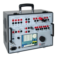
- Electrical connection of a time domain reflectometer: The SPG 40 can be combined with a TDR (e.g., Teleflex SX or T3060) for enhanced fault locating.
- Switching On: The AC mains connection must be plugged in, and the white push button [2] is pressed to start the SPG 40.
- Remote control using Teleflex SX: The SPG 40 can be controlled remotely via Teleflex SX, with the display showing the remote control mode.
- High Voltage control: The "HV enabled" mode is activated by pressing the green push button. The system ensures safety by checking for proper earthing and voltage discharge.
- Setup- Menu: Allows setting date/time, contrast, and language.
- Safety Menu: Displays the status of safety-related components (FU – stop voltage, FOHM loop resistance, Emergency Off Switch, External Emergency Off Switch, Key switch, Over temperature, System, HV connector, Earth connection, Rear door).
- Testing Mode: Includes Insulation Resistance Test, 40 kV – DC Proof Test, and Operation mode Breakdown Recognition.
- Fault Prelocating: Offers ARM (Arc Reflection Method), ICE (Impulse Current Equipment), Decay, and ICE-Plus methods.
- Pinpointing Mode: Features Acoustic method and Step Voltage Method.
- Burn Mode: Used to reduce fault resistance.
Maintenance Features
The manual provides guidance on care and maintenance to ensure the longevity and proper functioning of the SPG 40:
- General Maintenance: Instruments should only be worked on by de-energised instruments and by electrically skilled personnel.
- Installation and Operation: The instrument is not necessary to open the housing of the instrument. Opening the housing will void the warranty and liability of the manufacturer.
- Troubleshooting: Identify potential problems at an early stage and keep the system in good condition. This includes:
- Remove dust and dirt.
- Check the functionality of the emergency stop switch.
- Inspect the cables and connecting lines for cracks and damage.
- Yearly Safety Check: Megger recommends a yearly safety check of the instrument by a Megger service centre.
- Repair: Repairs should only be performed by Megger service personnel. If malfunctions occur, the instrument must be put out of operation and marked as not functional.
- Cleaning: The product may only be cleaned with the instrument turned off. High Voltage equipment must also be discharged and short-circuited. Under these conditions, a slightly wet towel may be used to wipe off the equipment. Aggressive cleaners and substances like acids should be avoided.
The SPG 40 is a robust and versatile fault locating system designed for efficient and safe operation in various cable testing and fault finding scenarios.