SD-6029, Rev 2
WARNING – This information contains technical data
subject to the EAR: ECCN: EAR99
Page 13 of 50
WARNING
Lifting hazard – Do not attempt to hand-lift the actuator. Use appropriate lifting
equipment.
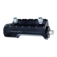
Mounting using the clevis
The ACT1000/ACT1000HF features a clevis for securing the motor end of the actuator. A
high-strength shoulder bolt (0.375” diameter) is recommended to fasten the actuator to a
user-provided mounting bracket.
The clevis can be rotated to any angular orientation to support installation. Loosen the four
retaining screws and rotate to the desired angle. The screw pattern can be indexed
± 45 degrees to provide additional adjustment. When adjustments are complete, torque the
four retaining screws to 117 to 138 in-lbf. It is important to use an opposing pattern and at
least 2 levels of torque to achieve the final value.
Mounting using the 4-bolt flange
The ACT1000/ACT1000HF can be flange mounted using the four (4) 5/16-24 UNF-3B female
threads located at the actuation end of the device. The threads utilize locking-type, high
strength stainless steel helical inserts.
The threaded portion of the mounting provision is recessed into the actuator body. To ensure
proper thread engagement length, it is important to choose an appropriate screw length to
accommodate the recess depth. Refer to Figure 1-5 for dimensional information regarding
the recess depth and full thread depth.
Connecting the extension rod
The extension rod has a 0.375-24 UNF-3B female thread for connecting user-supplied end
attachments with a 0.375-24 UNF-3A male thread. Thread depth is shown in Figure 1-5. It is
highly recommended to utilize an appropriately-sized spherical rod-end (a.k.a. ball joint)
attachment that will minimize any non-axial forces on the extension rod as it extends and
retracts.
Note: It is important that user-supplied end attachments and connecting hardware align
properly with the axis of travel of the extension rod. Any misalignment will result in a
side load on the extension rod (force applied perpendicular to the axis of the
extension rod) as it extends and retracts. Such loading will reduce the efficiency of
the ACT1000/ACT1000HF, requiring more electrical current to achieve a given
amount of force. A side load will also increase mechanical stress and friction,
increasing the rate of wear on the ACT1000/ACT1000HF.
 Loading...