SD-6029, Rev 2
WARNING – This information contains technical data
subject to the EAR: ECCN: EAR99
Page 9 of 50
Certifications
North American certifications Ex d IIB+H
2
T4 Gb IP66
Class I, Div 1, Group B, C, D T4
Class I, Zone 1, AEx d IIB+H
2
T4 Gb IP66
European Directive Compliance (CE Mark)
Ex db IIB + H
2
T4 Gb IP66
94/9/EC Potentially Explosive Atmospheres (ATEX)
2006/42/EC Machinery Directive
89/336/EEC Electromagnetic Compatibility Directive (EMC)
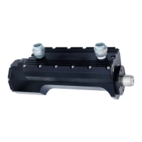
Materials
Housing Anodized 6061-T6 aluminum
Conduit unions Zinc-plated steel
Extension rod 17-4 PH CRES
Clevis
17-4 PH CRES
Weather seals Fluorocarbon and PTFE-based polymer
Extension rod sliding bearing
Aluminum bronze
Conduit union epoxy
Douglas Electrical Components part #: 29885/1470
Color: Blue
Overall dimensions
5.4 in x 6.1 in x 16.7 in (not including wiring conduits)
Weight
40 lbs
1.3 Mechanical installation
This section describes proper ACT1000/ACT1000HF installation. It is advised to confirm
compliance with factory recommendations.
Mounting orientation and product dimensions
The ACT1000/ACT1000HF can be mounted in any directional orientation, whether horizontal,
vertical, or at an angle. The actuator’s design allows two mounting types: the pin-mount type
using the provided clevis and the flange-mount type using the 4-bolt mounting flange.
Figure 1-3 shows envelope dimensions for the actuator. Figure 1-4 describes mounting
provisions for the pin-mount version while Figure 1-5 describes mounting provisions for the
flange-mount version. When utilizing the pin-mount, ensure that some clearance is factored
into mounting calculations to accommodate movement of the device.
 Loading...