10 Chapter III Dex CM3000
Full-Digital Control CO
2
/MAG/MIG Multi-FunctionWelding Machine
2. Turn the knob on the right panel to adjust F13 parameters (shown in table 3-6).
3. Shortpress “Function” key to exit from internal menu and F13 parameter settings is completed.
Table3- 6Parameter Table of Transition Time of Wire Feeding Speed
Function Code Unit Adjusting Range Step Length Default Value
F13 s
0.01~9.99S
0.01s 0.1s
Post-gas Time (F14)
Post-gas time after arc ending.
1. Enter into internalmenu by holding on “Function” key 3 seconds; turn the panel knob to F14.
2. Adjust the F14parameters, press“Function” again, F14 parameter settings is completed.
Table3-7Parameter Table of post-gas Time
Function Code Unit Adjusting Range Step Length Default Value
F14 s
0~25s
0.1s 1s
Wire InchingSpeed (F15)
The speed in which the wire is sent to the tip of the torch under the non-welding condition.
1. Enter into internal menu; turn the panel knob to F15. Press “Function” key, then the right LCD will be
twinkled.
2. Adjust F15 parameters by rotating the right knob (Table 3-8).
3. Press “Function”key againto exit from internal menu, F15 parameter settings is completed.
Table3-8 Parameter Table ofManual Wire Feeding Speed
Function Code Unit Adjusting Range Step Length Default Value
F15 m/min.
1.4~8 m/min.
0.1 m/min.
Automatic
Matching
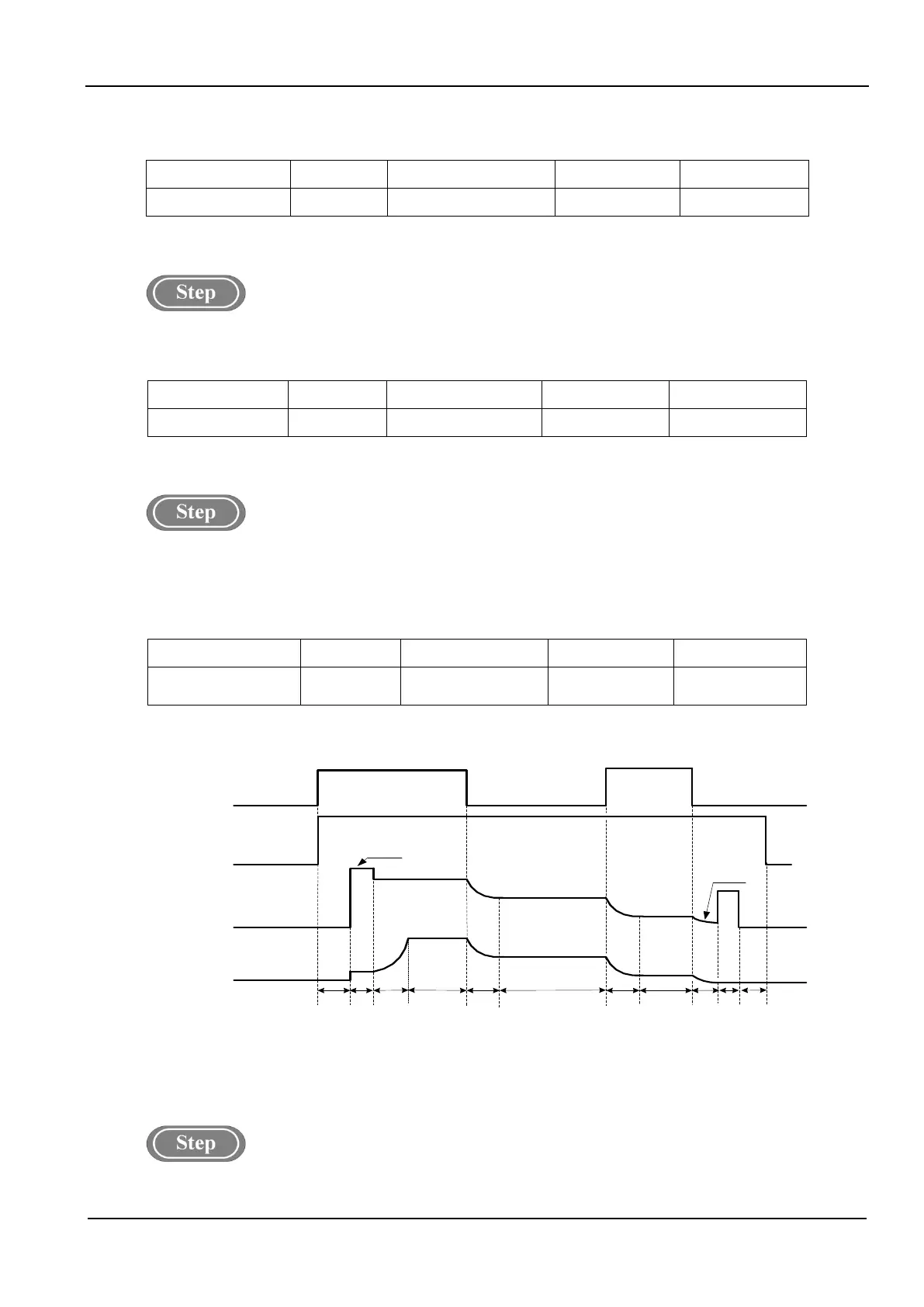
Logicdiagram of DC parameters.
As shown in the figure3-4.
Welding Torch
Switch
Gas Delivery
Welding
Voltage
Wire Feeding
Speed
(Welding Current)
Preflow
Gas
No-Load
Voltage
Arcing
Process
Welding Process
DC
Burn-
Back
Time
OFF
ON
OFF
ON
OFF
Arc-
Retreating
Process
Soft-
Start
Time
Transition
Time of Wire
Feeding Speed
Slow
Wire
feeding
DC
Chopping
Time
Burn-Back
Voltage
Transition
Time of Wire
Feeding Speed
Lagging Gas
Delivery
Fig.3-4Logic Diagram of DC Parameters(2T)
DC Burn-Back Voltage(F20)
1. Enter into internal menu by long pressing “Function” key; turn the panel knob to F20.
 Loading...