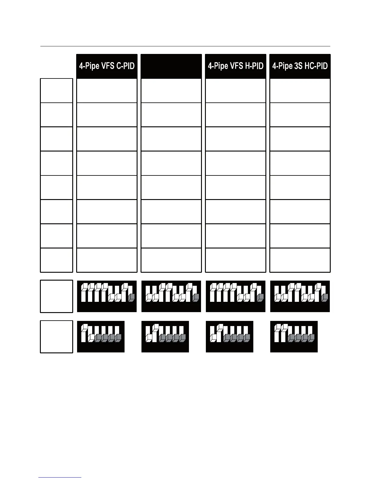
3. Wiring configuration and DIP Switches – Fan coil systems
-16 -
11
12
13
14
15
16
AO1
AO2
SW1
SW2
SW1.4 = Enable/Disable 2
nd
heating stage: ON – Enable, OFF – Disable
SW1.5 = Chilled beam option (fan will not run with 1
st
stage cooling) – SW1.5 ON
S2.3 – S2.6 – Not in use
C-PID = Cool valve PID H-PID = Heat valve PID
HC-PID = Cool and Heat valves PID VFS = Fan VFS
Heat element
Cool valve
X
Heat valve PID
Fan VFS
Heat element
X
X
Cool valve PID
Heat valve PID
87654321
654321
87654321
654321
Fan high
Fan medium
Fan low
Heat element
X
Heat valve
Cool valve PID
Fan VFS
4-Pipe 3S H-PID
Heat element
Cool valve
X
Heat valve PID
X
87654321
654321
87654321
654321
Fan high
Fan medium
Fan low
Fan high
Fan medium
Fan low
Fan high
Fan medium
Fan low