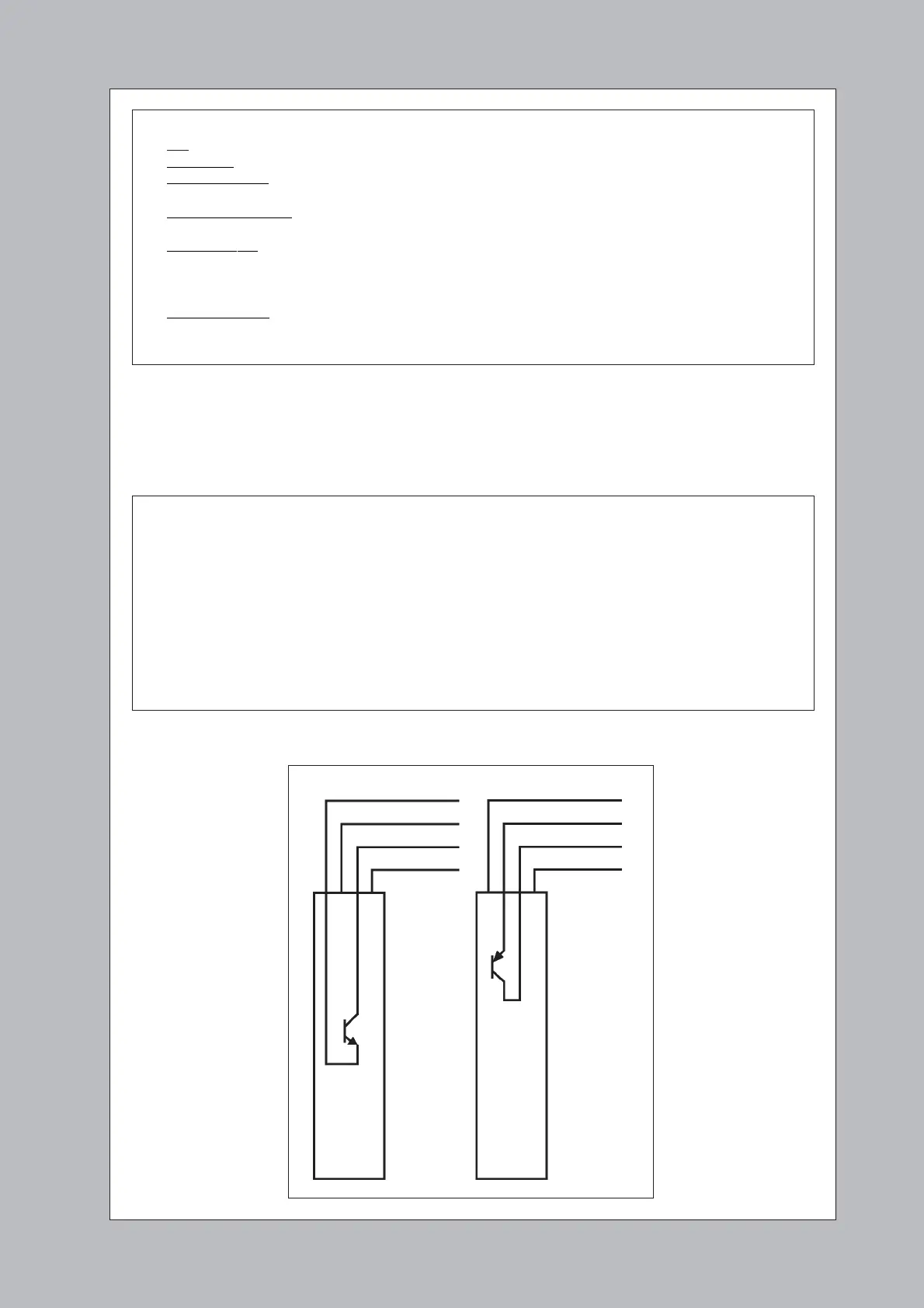
Fig 6: 618 Versions
The output transistor
inside the TX detector
3 Ensure all power to the lift is completely turned off while wiring the detectors.
4 Connect the TX and RX cables to a voltage-free terminal block on the lift car as shown in Fig 7. We
recommend always connecting the ‘0V’ (orange) wires first. Connect the car-top terminal block to the
lift controller or door operator using three wires as shown.
Check :-
• DC – do not use an AC supply;
• Regulated – do not use an unsmoothed supply;
• Negative Ground – do not use a ‘positive ground’ supply (since the orange 0V wire is connected to the
earthed metalwork);
• Common Referenced – the supply and 0V must be the same as for the ‘Door-Reopen’ circuit on the lift-
controller or door-operator. Beware of earth-loops.
• Correct Voltage – the voltage must be at least 11V and never exceed 36V DC under any circumstances.
Beware of any ripple or short transients on the supply. A standard DC voltmeter normally
measures the average voltage present – not the maximum voltage! Check carefully.
• Sufficient Power – the supply must be capable of supplying at least 100mA plus whatever current is
needed to drive the ‘Door-Reopen’ circuit on the lift.
Note - if you have any doubts then you should use a Model 280/281 Power Supply.
5 Turn on power to the system and fully test the installation.
Important
• Do not shorten Memco cables by cutting them. (Different wire colours may be used inside)
• Only use Memco cable between the RX/TX detectors and the car-top terminal block. (The Memco
cable is specially shielded. In particular, the white and orange wires carry sensitive data between
the TX and RX detectors and must only be connected using Memco cable)
• No more than three wires should go up the travelling cable to the lift controller (‘DC supply’, ‘0V’
and ‘Door Re-Open’).
• Ensure all cables are kept away from AC mains or high voltages.
• Be very careful not to confuse wire colours in the dim light of the lift shaft.
• ‘Timeout’ Option - Normally the timeout option is enabled by connecting the yellow wire to the
supply voltage (red wire) as shown in Fig 7. If desired it can be disabled by connecting the yellow
wire instead to 0V (orange wire).
NPN
Version
PNP
Version
0V (Orange)
DC Supply (Red)
Trigger Output (Blue)
Link (White)
0V (Orange)
DC Supply (Red)
Trigger Output(Blue)
Link (White)
 Loading...