5. Set SW2 and SW3 to match the version marked on the TX detector. (Usually this will be ‘PNP’ and ‘N C’ and
the switches will not require changing, but other combinations are possible).
6. Turn on power to the Model 280/281 and test the installation. A tone will be heard when a person or object
is detected. This tone can be disabled using SW1.
(b) Using Direct Connection
Often the 618 can be directly connected to the lift-controller or door-operator. In such cases the output
transistor inside the 618 TX detector directly drives the “door-reopen” circuit on the lift.
Warning – direct connection requires good understanding of both lift and detector electronics. Any incom-
patibility between the two systems may cause permanent damage to either. If you have any doubts then you
should use a Memco 280/281 Power Supply instead.
1 Check the ‘Door Reopen’ input on the lift is compatible with the 618 output transistor.
The 618 output transistor is factory-configured and cannot be changed afterwards. It may be NPN or PNP
as shown in Fig 6. It may also be Normally-Open (N/O) or Normally-Closed (N/C). Each versionhas a
different part number. The Memco standard is PNP-N/C because this provides a “failsafe” connection.
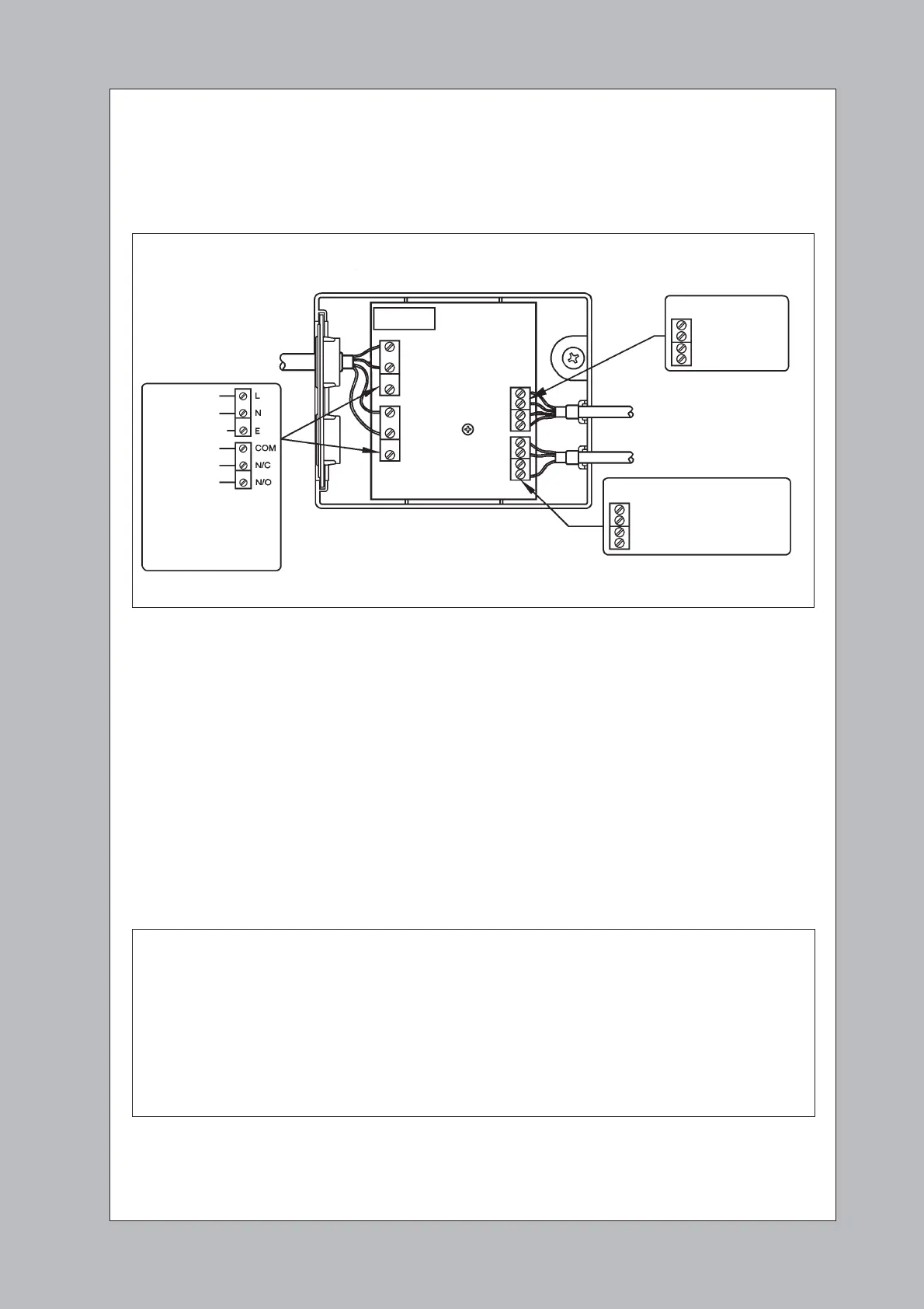
Model 280 or 281
TX CABLE
0V - ORANGE
+12V - RED
TRIG - BLUE
LINK - WHITE
RX CABLE
0V - ORANGE
+12V - YELLOW (Timeout Enabled)
LINK - WHITE
Power Supply
Door Re-Open
Circuit
TO LIFT CONTROLLER
OR DOOR OPERATOR
Fig 5: System Connection - Using a Model 280/281
2 Check the power source is suitable. This power source is normally provided by the lift-controller or door
operator.
Check:
• The ‘Door Reopen’ input accepts a transistor drive of the appropriate type.
• The ‘Door Reopen’ input is not connected to any other lift circuit (e.g. the ‘Reopen’ button inside the lift
car);
• The voltage on the transistor output (blue wire) will never be more than the supply voltage or less than
0V;
• The current through the transistor will never exceed 250mA (e.g. load resistance >150W);
• The current through the transistor will never be negative or AC;
Note - if you have any doubts then you should use a Model 280/281 Power Supply.
 Loading...