- 11 -
VIDEO IN ADJUSTMENT
1. Connect Pattern Generator (1Vp-p, Color Bar Pattern) to video jack (J701).
2. Connect positive lead of Oscilloscope probe 1 to R703 and negative lead of Oscilloscope to TP4 to
detect video in signal.
3. Connect positive lead of Oscilloscope probe 2 to TP10 and negative lead of Oscilloscope to TP4.
4. Select Video Mode by remote control.
5. Compare the waveform probe 2 with waveform probe 1.
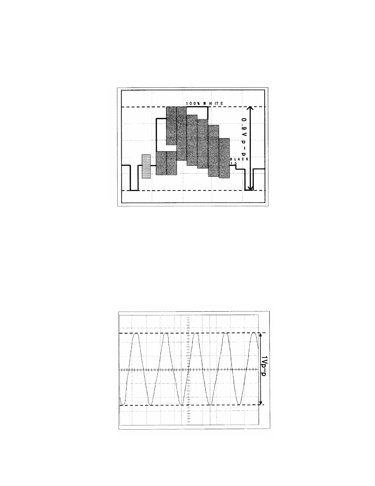
6. Adjust VR701 to get the waveform at TP10 and TP4 is 0.9Vp-p ± 0.1Vp-p same with the waveform at
probe 1. (Refer to Figure 7)
Fig. 7
AUDIO IN ADJUSTMENT
1. Connect Pattern Generator (1Vp-p, Color Bar Pattern) to video jack (J701).
2. Connect Audio Generator to audio jack (J702).
3. Connect positive lead of Oscilloscope probe 1 to R705 and negative lead of Oscilloscope to TP4 to
detect audio in signal.
4. Connect positive lead of Oscilloscope probe 2 to TP9 and negative lead of Oscilloscope to TP4.
5. Select Video Mode by remote control.
6. Compare the waveform probe 2 with waveform probe 1.
7. Adjust VR702 to get the waveform at TP9 and TP4 is 1.0Vp-p ± 0.05Vp-p same with the waveform at
probe 1. (Refer to Figure 8)
Fig. 8
 Loading...