TS510 & TS500
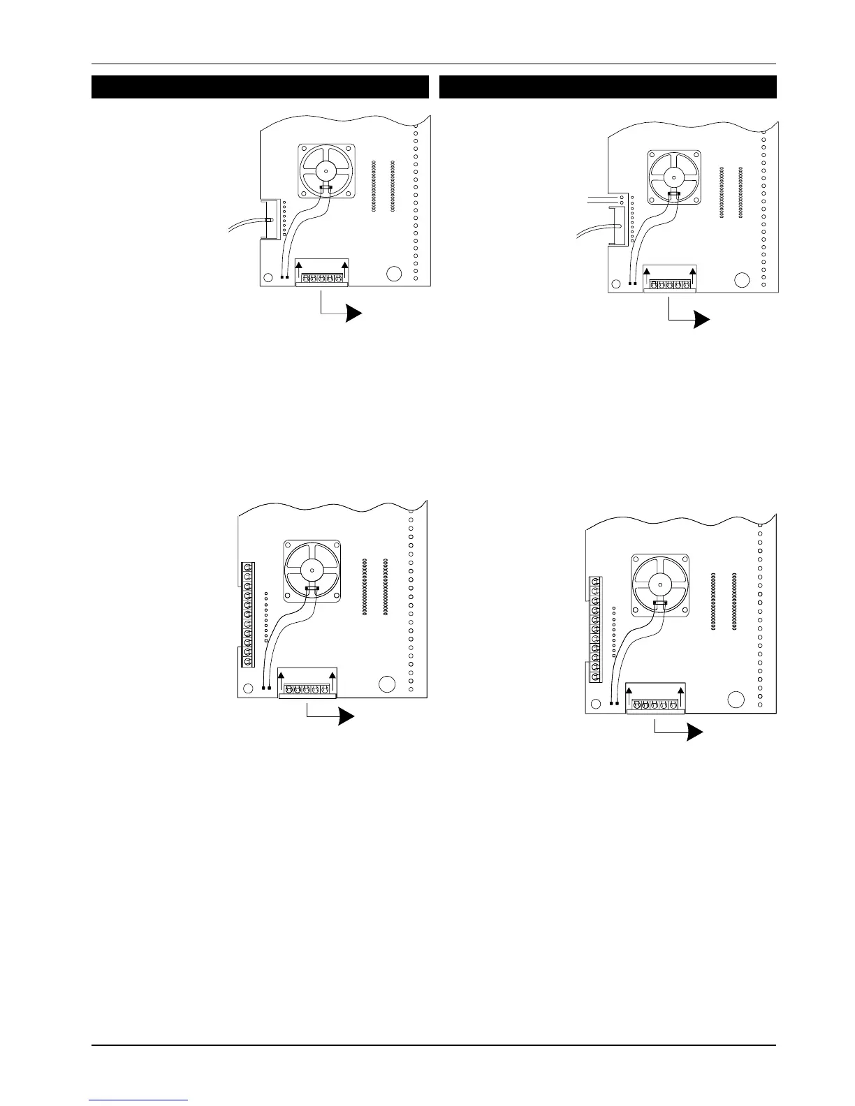
TS510 Digital Communicator Wiring
Fit the DC3 connector to the TS510 plug as shown.
Fit the TS510.IF to the panel plug taking care to ensure
that correct alignment is made and that no pins are
visible.
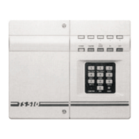
TS500 Digital Communicator Wiring
Fit the DC3 connector to the TS500 plug after
removing the polarity pin from socket 4. Ensure that
the connector is fitted with the wings pointing away
from the TS500 PCB, and the shorting link (or 2 spare
pins) are above the connector.
Remove the shorting link (if fitted) from the top 2 pins
of the DIGI INTERFACE connector. Fit the TS500/510.IF
to the panel plug taking care to ensure that correct
alignment is made and that no pins are visible.
496525 Issue A
5 of 10 TS510 & TS500
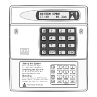
TO REMOTE
KEYPAD
TO DC 3.
DC 3 CHANNELS
1=FIRE
2=PA
3=ALARM
ERMINAL BLOCKS (top to bottom)
LINE FAULT (+ve applied during line fault)
0V
12V
8=SOUNDERON
7=BELLON
6=PARTSET
5 = ENGINEER - ON - SITE
4=SET/UNSET
3=ALARM
2=PA
1 = FIRE
LF
0V
12V
8
7
6
5
4
3
2
1
Fig 6 TS500/510.IF and TS500.REM Connections
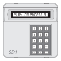
TO REMOTE
KEYPAD
REMOTE INTERFACE
DIGI
INTERFACE
ERMINAL BLOCKS (top to bottom)
LINE FAULT (+ve Applied in Line Fault)
0V
12V
8=FAULT
7 = DET RESET
6 = SW 12V
5 = ENGINEER - ON - SITE
4=SET/UNSET
3=ALARM
2=PA
1 = FIRE
LF
0V
12V
8
7
6
5
4
3
2
1
Fig4 TS510.IF and TS510.REM Connection
TO REMOTE
KEYPAD
TO DC 3.
DC 3 CHANNELS
1=FIRE
2=PA
3 = ALARM