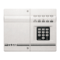
TS510 & TS500
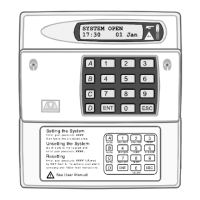
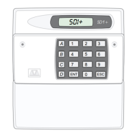
Remote Keypad
Up to 4 remote keypads (order code: TS510 REM), can
be fitted, these are supplied with an interface which
plugs onto the main panel PCB. The connections from
the panel to the Remote Keypad require a five core
cable (max length 50m).
Assuming that the control panel covers have been
removed, the cable is in place and that the mains
supply and backup battery have been disconnected,
installation is as follows:
1. Connect the cable to the interface connections A,
B, C etc, and then carefully locate the interface in
theslotatthebottomofthepanelPCB. Replacethe
right hand cover assembly.
2. Separate the remote keypad cover assembly from
the base by releasing the clips on the top and
bottom of the housing. Place the base on the wall
where it is required and mark the screw positions.
Removethebasethen drillandplugthewall. Fixthe
base to the wall.
3. Taking care not to damage the PCB assembly,
connect the terminal blocks on the remote keypad
to the cable, ensuring that the connections through
to the control panel interface card are A to A, B to B
etc.
4. Carefully re-attach the front cover assembly to the
baseensuringthatthecable isclearof thespringon
thetamperswitch,andthecoverissecurelyclipped
to the base. Finally re-connect the mains supply
and test the operation of the remote keypad.
5. If more than 1 remote keypad is to be used,
connections may be in a star or daisy chain
configuration.
NOTE: TS500 only compatible with TS500 REM.
NOTE: TS500 only, link (LKI). If open the remote
keypad will have full functions if closed you
can only use remote keypad to set, part set
and unset.
NOTE: TS500 Only one remote keypad can be fitted
Digital Communicator
The DC3 is an 8 channel plug-on digital communicator
specifically designed to operate with Menvier Security
control panels, and is supplied with a lead for
connection directly onto the main panel PCB. The unit
has its own installation and programming instructions
which must be referred to before proceeding with
installation. The digital communicator is mounted
behind the right hand lid assembly as appropriate.
CAUTION: The mains supply and backup battery must
be disconnected before connecting the DC3 to the
main PCB.
Other communication devices such as the DC28
Digicom,RedCARESTU,PakentInterfaceCardetc. may
be connected to the TS510 by using an optional
interfacecard(TS510.IF). This isalsosupplied withitsown
installation instructions which should be referred to
before proceeding with installation. Fig. 4 shows the
TS510.IF connections when plugged onto the TS510
PCB. (See page 5)
TS510 & TS500 4 of 10 496525 Issue A