This document describes the Mercator Remote Controller for Ceiling Fans, models FRM87 and FRM87GL. It serves as an installation and operation instruction book, emphasizing safety precautions, installation procedures, and functional operation of the remote control system.
Function Description:
The Mercator Remote Controller is designed to provide wireless control over ceiling fans, including their speed and integrated light kits. It allows users to turn the fan on/off, adjust fan speed (high, medium, low), and toggle the fan light on/off using a handheld transmitter. The system operates on an AC240V, 50Hz power supply and is intended for indoor use only. A key feature is the ability to set unique code switches for both the transmitter and receiver, enabling independent operation of multiple ceiling fans within the same vicinity, preventing interference between units.
Important Technical Specifications:
- Power Supply: AC240V, 50Hz (for ceiling fan operation).
- Battery: 9V battery for the remote control transmitter.
- Compatibility: Designed for use with ceiling fans. Not to be used with variable (rheostat) wall controls.
- Installation: The receiver must be installed within the ceiling fan canopy. If the receiver cannot fit due to dimensional limitations or if the fan has a low-profile/hugger design without a suitable hanging bracket, it can be enclosed in an Electrical Insulation Box (following Australian wiring regulations) and placed in the ceiling. The antenna wire should be drawn away from the insulation box through a small hole in such cases.
- Isolation Switch: The power supply to the remote control receiver must be connected through an isolation switch (e.g., an existing wall switch) for safety and proper operation.
- Code Switch: Features a 4-position DIP switch for setting unique operational codes, allowing for 16 possible combinations (0000 to 1111, where 1 represents ON and 0 represents OFF).
Usage Features:
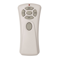
- Fan Speed Control:
- HI: Press once to turn on the fan at high speed.
- MED: Press once to turn on the fan at medium speed.
- LOW: Press once to turn on the fan at low speed.
- OFF: Press once to turn off the fan.
- Light Control:
- LIGHT (bulb icon): Press once to toggle the light on or off.
- Code Switch Setting: Before operation, the code switch settings on both the transmitter and receiver must be identical. This prevents interference and allows for independent control of multiple fans.
- Initial Setup for Pull Chain Fans: For ceiling fans equipped with manual or pull chain switches, the fan must be set to HIGH speed and the light kit (if any) to the ON position using the pull chain after installation, before operating with the remote control.
- Isolation Switch Usage: The isolation switch (wall switch) must be turned on before operating the remote controller and turned off when not in use.
Maintenance Features:
- Battery Replacement: The remote control transmitter requires a 9V battery. A weakening battery is indicated when the transmitter needs to be held increasingly closer to the fan to operate. Users are advised to replace the battery before it leaks, as leakage can damage the transmitter. Used batteries should be disposed of properly and kept out of reach of children.
- Wiring Integrity: During installation, care must be taken not to pull on or cut leads shorter, or to drop or bump the unit. The antenna should be kept safely inside the canopy, and its wiring should not be cut or damaged.
- Professional Installation: Installation of this product must be undertaken by a licensed and qualified electrician in accordance with SAA and local authority regulations. This ensures proper and safe installation, minimizing risks of fire or injury.
- General Care: The product should not be installed in damp locations or immersed in water. Users are reminded to apply common sense and care during all phases of installation and operation.