INSTALLATION
45
• Shift side: Set the shift cable to the cable clip and insert the
lock pin at the shift lever fitting hole and turn it 90° to lock it.
40470
a
b
c
d
e
f
g
h
i
j
k
l
m
n
o
p
q
r
s
t
u
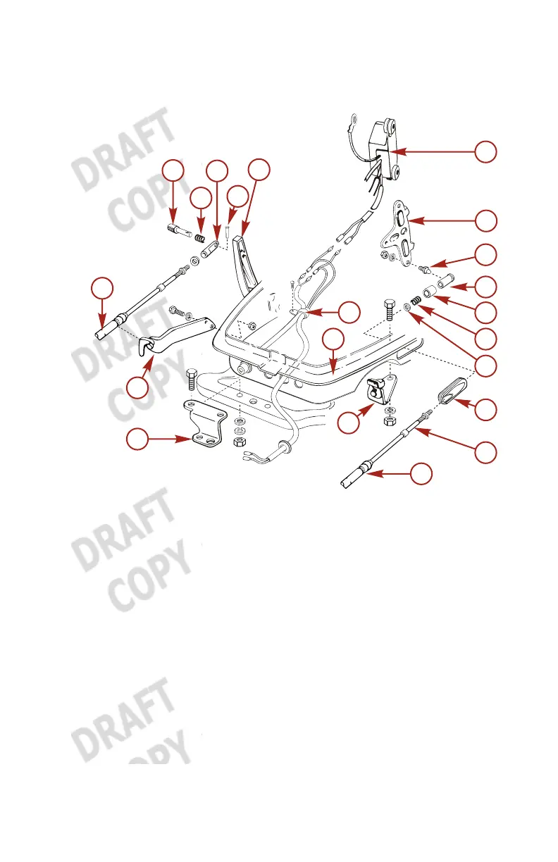
a - Cable of the shift side
b - Cotter pin
c - Spring
d - Sleeve B guide
e - Spring pin
f - Shift lever
g - CD unit
h - Advancer arm
i - Ball joint
j - Ball holder
k - Holder cap
l - Spring
m -Washer
n - Grommet B is installed on
the lower cowl
o - Cable of the throttle side
p - Cable outer groove
q - Cable clip
r - Lower cowl
s - Clamp
t - Steering hook plate
u - Shift cable clip
NOTE: Put the control lever on the Neutral (N) position and the
Neutral warm‑up lever in the fully closed position.
 Loading...