EasyManua.ls Logo

Mercury 8M6009517 - User Manual

Mercury 8M6009517
6 pages
Print Icon
To Next Page IconTo Next Page
Loading...
90-8M0172030 eng JULY 2020 © 2020 Mercury Marine Page 1 / 6
SMARTCRAFT/NMEA 2000 GPS
IMPORTANT: This document guides our dealers, boatbuilders, and company service personnel in the proper installation or
service of our products. If you have not been trained in the recommended servicing or installation procedures for these or
similar Mercury Marine products, have the work performed by an authorized Mercury Marine dealer technician. Improper
installation or servicing of the Mercury product could result in damage to the product or personal injury to those installing or
operating the product. Always refer to the appropriate Mercury Marine manual for component removal and installation
instructions.
NOTE:
After completing installation, place these instructions with the product for the owner's future use.
Components Contained in Kit
71440
1
2
3
4
Ref. No. Qty. Description
1 1 GPS sensor
2 1 Under helm bracket
3 2 Screws, wood #8 (5.4 mm (0.21 in.) x 13 mm (0.51 in.))
4 4 Deck mounted bracket
!
WARNING
Use of this GPS as a navigational source for any automatic pilot system where that system has control of the vessel
heading, steering systems, trolling motors, or engines could result in serious injury or death from the loss of vessel control.
These referenced automatic piloting systems include but are not limited to Mercury Marine joystick and electric steering
systems in all configurations.
Certification
NMEA 2000 load equivalency number (LEN)
2
NMEA certification
Yes
Product name
Mercury SmartCraft/N2K GPS
Description
Mercury GNSS receiver for SmartCraft or N2K applications
Manufacturer code
144‑Mercury Marine
Product code
27251
Class code
60‑Navigation
Function code
145‑Ownship position (GNSS)
Mounting Requirements
IMPORTANT: The GPS sensor connection is considered a drop off of the CAN bus or NMEA network. Ensure that the
installation of the GPS sensor does not exceed CAN bus length specifications.
IMPORTANT: The installation location must take into account the following requirements:
Question and Answer IconNeed help?

Do you have a question about the Mercury 8M6009517 and is the answer not in the manual?

Summary

Components Contained in Kit

Certification

Mounting Requirements

Elevation (above vs below deck)

Describes mounting the GPS sensor above or below the deck for optimal performance.

All Location Requirements

Mount GPS sensor near vessel's center of gravity, away from hazards and excessive vibration.

Electromagnetic Interference (EMI)

Avoid mounting near strong EMI sources like engines or antennas to prevent signal loss.

Vessel construction

Do not mount where boat structure contains large metallic or reflective surfaces.

Prevailing conditions

Calm weather is optimal; high latitudes or below-deck mounting may reduce accuracy.

GPS Sensor and Connector Clearance Dimensions

Under Helm Bracket and Connector Clearance Dimensions

Provides clearance dimensions for mounting the GPS sensor under a helm or bulkhead.

Sensor Installation

GPS Sensor Mounting

Details the process for installing the GPS sensor, emphasizing vessel standstill.

Deck Mounted Bracket

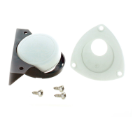
Step-by-step guide for mounting the GPS sensor bracket on the deck.

Under Helm or Bulkhead Mounting

Step-by-step guide for mounting the GPS sensor under a helm or bulkhead.

GPS Sensor Connections

GPS Sensor Connection-CAN P

Diagram and explanation for connecting the GPS sensor via CAN P.

GPS Sensor Connection-NMEA 2000

Diagram and explanation for connecting the GPS sensor via NMEA 2000.

Verification

For Mercury Marine Active Trim feature

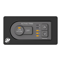
Tests the GPS sensor's functionality with the Mercury Marine Active Trim.

NMEA 2000 PGN Information

Overview

This document describes the installation and connection of the SmartCraft/NMEA 2000 GPS sensor, a device designed to provide GPS data for marine applications. It is fully compatible with both Mercury SmartCraft and NMEA 2000 communication networks.

Function Description

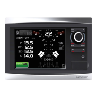
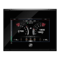
The GPS sensor acts as a Mercury GNSS receiver for SmartCraft or N2K applications, providing essential navigation data. Its primary function is to supply position information (GNSS) and other related data to various marine devices, including chartplotters, SmartCraft gauges, and multifunction displays (MFDs). The sensor supports several NMEA 2000 PGNs (Parameter Group Numbers), enabling it to transmit a wide range of data, including:

  • ISO Request (PGN 59904)
  • ISO transport protocol (PGN 60160, 60416)
  • ISO address claim (PGN 60928)
  • PGN List (PGN 126464)
  • System time (PGN 126992)
  • Heartbeat (PGN 126993)
  • Product information (PGN 126996)
  • Configuration information (PGN 126998)
  • Position, rapid update (PGN 129025)
  • COG and SOG, rapid update (PGN 129026)
  • GNSS position data (PGN 129029)
  • GNSS DOPs (PGN 129539)
  • GNSS sats in view (PGN 129540)

This comprehensive data output allows for accurate navigation, speedometer functions, and integration with advanced systems like Mercury Marine's Active Trim feature. For Active Trim, the GPS sensor is designed to automatically connect to the Active Trim controller, enhancing its functionality.

Important Technical Specifications

  • NMEA 2000 Load Equivalency Number (LEN): 2
  • NMEA Certification: Yes
  • Product Name: Mercury SmartCraft/N2K GPS
  • Description: Mercury GNSS receiver for SmartCraft or N2K applications
  • Manufacturer Code: 144-Mercury Marine
  • Product Code: 27251
  • Class Code: 60-Navigation
  • Function Code: 145-Ownship position (GNSS)
  • Dimensions (GPS Sensor):
    • Height: 60.7 mm (2.39 in.)
    • Diameter: 18.5 mm (0.73 in.)
    • Connector Clearance: 76.2 mm (3 in.)
  • Dimensions (Under Helm Bracket):
    • Length: 102.5 mm (4.03 in.)
    • Width: 32 mm (1.26 in.)
    • Connector Clearance: 76.2 mm (3 in.)
  • Mounting Hardware: Wood screws #8 (5.4 mm (0.21 in.) x 13 mm (0.51 in.))
  • Hole Saw Size for Harness Pass-Through: 22 mm

Usage Features

The GPS sensor offers flexible mounting options, either on the deck or under the helm/bulkhead, to suit various vessel configurations.

  • Optimal Performance: Mounting the sensor above decks with a clear, unobstructed view of the sky in all directions provides optimal GPS sensor performance. While mounting below decks with only fiberglass between the sky and the sensor is possible, it may result in reduced performance. Mounting in locations with significant obstructions is not recommended.
  • Location Requirements: The sensor should be mounted close to the vessel's center of gravity to minimize the impact of pitch and roll on position reporting. It must be installed in an area free from physical damage, excessive vibration, or heat.
  • Electromagnetic Interference (EMI) Mitigation: To prevent poor performance and loss of satellite signals, the sensor must be mounted a minimum of 0.91 m (3 ft) away from engines, radio antennas, and radar antennas. It should not be in the direct path of any radar antennas.
  • Vessel Construction Considerations: Avoid mounting the sensor near large metallic or reflective material surfaces, as these can interfere with signal reception.
  • Environmental Factors: Calm and clear weather conditions are ideal for GPS sensor accuracy. Operating in extreme North or South latitudes or sub-optimal conditions may reduce signal strength, especially for sensors mounted below decks.
  • NMEA 2000 Network Integration: The GPS sensor connects as a drop-off from the CAN bus or NMEA network. It is crucial to ensure that the installation does not exceed CAN bus length specifications.
  • Installation Process: The installation involves marking and drilling holes for the bracket and harness pass-through, applying marine-grade sealant for weatherproofing, and securely attaching the bracket and sensor. Strain relief for the cable is also recommended.

Maintenance Features

While the document does not explicitly detail maintenance features, it emphasizes proper installation to ensure longevity and optimal performance.

  • Weatherproofing: The use of weather-proof marine-grade sealant during deck mounting is crucial to protect the sensor and connections from water ingress, which is a key aspect of preventing damage and ensuring long-term functionality.
  • Secure Connections: Hand-tightening NMEA 2000 harness ends onto the GPS NMEA receptacle, being careful not to cross-thread, ensures a secure and reliable connection, minimizing the risk of intermittent signal loss.
  • Strain Relief: Creating a strain relief in the cable and attaching it to the under helm bracket spur with a cable tie helps prevent stress on the connections, reducing the likelihood of cable damage over time.
  • Verification: After installation, verifying the GPS sensor's presence on the network device list of an NMEA 2000 MFD or Mercury Marine MFD/SmartCraft Gauge is essential. For SmartCraft capable gauges (System Tachometer, System Speedometer, MercMonitor), users should refer to their respective operations manuals to correctly source the GPS sensor and test its operations. This verification step ensures the sensor is properly recognized and functioning within the vessel's network.

This GPS sensor is a critical component for modern marine navigation systems, offering reliable position data and seamless integration with Mercury Marine's ecosystem. Proper installation according to the provided guidelines is paramount for achieving optimal performance and ensuring the safety of the vessel.

Mercury 8M6009517 Specifications

General IconGeneral
BrandMercury
Model8M6009517
CategoryMarine Equipment
LanguageEnglish

Related product manuals