EasyManua.ls Logo

Mercury 4000 MPC GEN 2 - User Manual

Mercury 4000 MPC GEN 2
23 pages
Print Icon
To Next Page IconTo Next Page
Loading...
90-899782001 APRIL 2008 © 2008 Mercury Marine Page 1 / 23
4000 MPC GEN 2 PISTOL GRIP REMOTE
CONTROL INSTALLATION/OPERATION
INSTRUCTIONS
IMPORTANT: This document guides our dealers, boatbuilders, and company service
personnel in the proper installation or service of our products. If you have not been trained
in the recommended servicing or installation procedures for these or similar Mercury
Marine products, have the work performed by an authorized Mercury Marine dealer
technician. Improper installation or servicing of the Mercury product could result in
damage to the product or personal injury to those installing or operating the product.
NOTE:
After completing installation, place these instructions with the product for
the owner's future use.
Pistol Grip Remote Control with Finger Tip Neutral Lock Release
24953
Notice to Installer/Owner
Safety Alerts and Notices
Throughout this publication, "Warnings" and "Cautions," accompanied by the
international HAZARD symbol
!
, are used to alert the technician to special
instructions concerning a particular service or operation that may be hazardous if
performed incorrectly or carelessly. Observe these safety alerts carefully.
These safety alerts alone cannot eliminate the hazards they signal. Strict compliance to
these special instructions when performing the service, and common sense operation are
major accident prevention measures.
Question and Answer IconNeed help?

Do you have a question about the Mercury 4000 MPC GEN 2 and is the answer not in the manual?

Summary

Notice to Installer;Owner

Safety Alerts and Notices

Alerts technicians to special instructions concerning hazardous operations.

GEN 2 Pistol Grip Remote Control Features

Neutral Lock Button Operation

Prevents unintentional shifting into gear; press and hold to shift.

Throttle Only Button Operation

Allows throttle advancement without shifting; used for starting engine.

Power Trim Switch Function

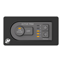
Used to trim or raise drive unit for trailering, launching, or shallow water.

Lanyard Stop Switch Function

Purpose is to stop engine if operator moves far from station.

Remote Control Cable Management

Remote Control Cable Selection and Routing

Guidance on selecting correct cables, including bend radius and length.

Shift and Throttle Cable Lubrication

Details lubrication points for shift and throttle cables with 2-4-C with Teflon.

Panel Mount Control Installation

Mounting Clearances and Bezel Location

Defines minimum clearances for panel mount controls and bezel mounting.

Bezel Installation Procedure

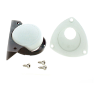
Steps for locating, drilling, and securing the bezel for panel mounting.

Shift and Throttle Cable Installation

Anchor Attachment and MerCruiser Setup

Details anchor points for various models and MerCruiser rotation setup.

Pistol Grip Control Installation

Trim Switch and Handle Assembly Installation

Procedure for routing trim switch wires and installing the control handle assembly.

Throttle-Only Button Removal

Wiring Diagrams

Outboard and Gasoline Engine Wiring

Wiring diagrams for Mercury outboards and MerCruiser gasoline engines.

MerCruiser Diesel Engine Wiring

Wiring diagrams for Mercury MerCruiser D1.7L, D3.0L, D3.6L, D4.2L Diesel engines.

GEN 2 Bezel Template

Template Usage and Mounting

Guidance on using the bezel template for cutting holes and mounting the control module.

Overview

This document describes the 4000 MPC Gen 2 Pistol Grip Remote Control, an installation and operation manual for a marine remote control unit. It is designed for use with Mercury, Mariner, Force, and Mercury MerCruiser engines.

Function Description:

The 4000 MPC Gen 2 Pistol Grip Remote Control is a panel-mount unit that provides control over the engine's shift and throttle functions, as well as power trim. It features a pistol grip design with a finger-tip neutral lock release for enhanced control and safety. The unit allows for both standard and counter-rotation drive unit applications, with specific cable installation instructions provided for each.

Key operational features include:

  • Neutral Lock Button: This button prevents unintentional shifting into gear. To engage a gear, the neutral lock button must be pressed and held while moving the control handle out of neutral.
  • Throttle Only Button: This feature allows for throttle advancement without engaging the shift mechanism. It disengages the shifting mechanism from the control handle and can only be pressed and held when the control handle is in the neutral position. This is useful for assisting in engine starting.
  • Power Trim Switch: (If equipped) This switch is used to trim or raise the drive unit for various operations such as trailering, launching, beaching, or shallow water navigation.
  • Lanyard Stop Switch: (If equipped) The primary purpose of this switch is to immediately turn off the engine if the operator moves far enough away from their position (e.g., in case of accidental ejection). The lanyard is typically 122 to 152 cm (4 to 5 feet) long when stretched and is designed to be attached to the operator. The manual emphasizes the critical safety role of this switch in preventing serious injury or death from being struck by the boat after an operator falls overboard. It also warns against accidental activation during normal operation, which could lead to unexpected loss of forward motion, loss of power and directional control, or loss of control when docking.
  • Control Handle: This is the primary interface for operating the shift and throttle. Pushing the handle forward from neutral engages forward gear and increases speed, while pulling it back from neutral engages reverse gear and increases speed. A "quick firm motion" to the first detent is specified for engaging gears.
  • Control Handle Friction Adjustment Nut: This nut allows the operator to increase or decrease the tension on the control handle, which helps prevent "creep" of the handle. It is factory set but can be adjusted to a desired tension.

Important Technical Specifications:

  • Cable Requirements: GEN 2 control cables are mandatory for use with GEN 2 remote controls. The cables must be of the correct length to avoid kinks (if too short) or unnecessary bends/loops (if too long), both of which can stress the cables and impair shift/throttle operation.
  • Minimum Bend Radius: The minimum bend radius for remote control cables is 30.5 cm (12 in.). For applications requiring smaller radii or lengths exceeding 5.5 m (18 ft.), Mercury/Quicksilver GEN 2 Platinum or Premium cables are required.
  • Mounting Clearance: A minimum of 45.7 cm (18 in.) straight routing clearance is required for the control cables exiting the remote control module. No anchors, clamps, cable ties, or other items should be secured within this clearance area.
  • Mounting Panel Thickness: The mounting surface for the bezel should be a flat and rigid platform, preferably aluminum, fiberglass, or plywood reinforced with fiberglass. The mounting platform thickness must not exceed 2.54 cm (1 in.) for a robust installation.
  • Control Handle Friction: Factory preset, but adjustable. Proper friction is crucial for mechanical control operation; insufficient friction can lead to undesirable throttle arm operation.
  • Torque Specifications:
    • Bezel mounting screws (3): 5.6 Nm (50 lb. in.) for aluminum or fiberglass; 4 Nm (35 lb. in.) for plywood.
    • Cable fastener screws: 2.8 Nm (25 lb. in.). Loctite 271 Threadlocker is required for these screws, especially if they have been previously installed and removed.
    • Back plate screws (5): 0.57 Nm (5 lb. in.).
    • Control module mounting screws (3): 5.6 Nm (50 lb. in.).
    • Control handle retaining bolt: 17 Nm (150 lb. in.). Loctite 271 Threadlocker is required for this bolt.
  • Neutral-Safety-Protection Device: The manual explicitly states that starting the engine with the drive in gear can cause serious injury or death, and a boat should never be operated without a neutral-safety-protection device.

Usage Features:

  • Panel Mount Design: The control unit is designed for panel mounting, typically on the starboard side of the boat.
  • Ergonomic Pistol Grip: The pistol grip design is intended for comfortable and intuitive operation.
  • Finger Tip Neutral Lock Release: This feature allows for quick and easy engagement of gears while maintaining safety.
  • Adjustable Control Handle Friction: Allows operators to customize the feel and tension of the control handle to their preference, preventing unwanted handle movement.
  • Shift and Throttle Cable Installation: Detailed instructions are provided for connecting shift and throttle cables, including specific anchor attaching locations for various outboard and MerCruiser models (standard and counter-rotation).
  • Wiring Diagrams: Comprehensive wiring diagrams are included for the lanyard stop switch for Mercury/Mariner Outboards and Mercury MerCruiser Gasoline and Diesel models, detailing connections for neutral start safety leads, ignition key switch, engine harness, power trim, and trim limit switches.
  • Bezel Template: A template is provided for accurate cutting and drilling of mounting holes, with a note to verify the template against the actual bezel due to potential printing variables. The module can be rotated in 30° increments during mounting.

Maintenance Features:

  • Lubrication: Shift and throttle cables require lubrication with 2-4-C with Teflon at specified points to ensure smooth operation.
  • Threadlocker Application: Loctite 271 Threadlocker is specified for cable fastener screws and the control handle retaining bolt, indicating a need for secure, vibration-resistant fastening.
  • Edge Deburring: After cutting and drilling mounting holes, all sharp edges must be removed to prevent chafing of harnesses.
  • Trim Switch Lead Management: Crucial instructions are given to ensure trim switch leads have sufficient slack and are not pinched during installation, as this could lead to a trim system failure. No cable ties should be used near the control module to restrain these leads.
  • Control Handle Friction Adjustment: This is a user-adjustable feature that can be performed as needed to maintain desired control handle tension. It must be done before the remote control module is fully installed onto the bezel.
  • Throttle-Only Button Removal: Instructions are provided for removing the throttle-only button, which may be necessary for maintenance or adjustment. Care is advised to protect the painted control handle during this process.

Mercury 4000 MPC GEN 2 Specifications

General IconGeneral
BrandMercury
Model4000 MPC GEN 2
CategoryMarine Equipment
LanguageEnglish

Related product manuals