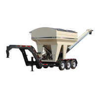
The Meridian 240 FF Basic Seed Express™ Bulk Seed Tender is a specialized agricultural machine designed for efficient and safe handling and delivery of bulk seeds to planters. This operator's manual provides comprehensive information on its function, technical specifications, usage, and maintenance.
Function Description
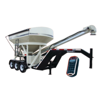
The Meridian 240 FF Basic Seed Express™ Bulk Seed Tender serves as a mobile seed delivery system, allowing farmers to transport large quantities of seeds and efficiently load them into planters or drills. Its primary function is to streamline the seeding process, reducing downtime and labor associated with traditional seed handling methods. The tender features multiple compartments for different seed types or varieties, a conveyor system for controlled discharge, and a robust trailer for transport. The design emphasizes safety, ease of operation, and durability in agricultural environments.
Important Technical Specifications
The tender is equipped with a hydraulic pump that powers the hydraulic motor for the conveyor belt and the hydraulic cylinder for raising and lowering the conveyor tube. The conveyor system is designed to rotate 180 degrees, allowing for flexible positioning during seed delivery. The conveyor tube features a pivot base to secure the tube and turret, and a telescoping delivery spout for precise placement.
Dimensions (approximate):
- Overall Length: 24' 1"
- Overall Width: 8' 5" (8' 0" at top)
- Overall Height: 12' 6" (11' 4" when lowered, 1' 11" in transport)
- Trailer Height: 19"
- Conveyor Tube Length: 10' 0"
- Discharge Height: Up to 11' 1" (at 32° angle)
- Ground Clearance: 8' 3"
Capacities:
- Fuel Tank: 6.4 US quarts (6.1 liters)
- Crankcase: 1.16 US quarts (1.1 liters)
- Hydraulic Oil Reservoir: 10 US Gallons (37.8 Liters) of ISO grade 32 fluid (AW HVI or comparable).
Tires:
- Part Number: 18131 or an equivalent tire: 3T235/80R16
- Load Range: E
- Tire Pressure: Refer to the tire sidewall for information on the maximum cold tire pressure (PSI). Keep the tires inflated to this setting.
Wheel Bearings:
- Each axle is equipped with a grease zerk under the center dust cap of the wheel. Add grease sparingly to the wheel bearings using only wheel bearing grease. The wheel bearings should be repacked annually.
Bolt Torque:
The manual provides detailed English and Metric torque specifications for various bolts and capscrews, emphasizing the importance of correct torque for safety and performance. For example, a 1/4" SAE 2 bolt requires 8 ft-lb (12 Nm), while a 1" SAE 8 bolt requires 345 ft-lb (470 Nm). Metric bolts like an M3 8.8 require 0.5 ft-lb (0.4 Nm), and an M36 10.9 requires 2600 ft-lb (3917 Nm).
Usage Features
Operation Orientation: The manual emphasizes the importance of reading and understanding the entire manual, including all safety and maintenance information, before using or maintaining the bin.
Safety Decals: The machine is equipped with various safety decals (e.g., 19935, 19936, 19937, 19984, 10479, 20088) that provide warnings and instructions. It is crucial to read and understand all decals and replace any that are missing or illegible.
Work Preparation:
- Personal Protective Equipment (PPE): Always wear a hard hat, eye protection, protective shoes, and work gloves.
- Placement Safety: Stay away from overhead obstructions and power lines. Electrocution can occur without direct contact.
- Lock-Out Tag-Out Safety: Establish a formal Lock-Out Tag-Out program for your operation.
- Noise Level: Noise over 85 dB on a long-term basis can cause severe hearing loss. Noise over 90 dB adjacent to the operator can cause permanent, total hearing loss. Hearing loss from loud noise (tractors, chain saws, radios, etc.) is cumulative over a lifetime without hope of natural recovery.
Attaching to Tow Vehicle:
- Hitch: The bumper hitch trailer is equipped with a jack at the nose. It is important to lower the jack when using the tender to give stability.
- Safety Chain: Attach the safety chain securely to the tow vehicle to prevent unexpected separation. Cross the chains when attaching.
- Break-Away System: Connect the break-away system cable to the tow vehicle. Plug the key on the end of the cable into the receiving unit.
- Wiring Harness: Connect the wiring harness for the lights and brakes.
- All Cables: Route all cables in a manner that will prevent snagging. Be sure to provide slack for turning.
Roll-Up Tarp:
- Opening: Unclip and remove the crank handle. Extend the crank rod to a comfortable operating position. Roll the tarp to the fully opened position.
- Closing: Return the crank handle back into the holder and close to secure. Use the ratchet straps and cables to tension the roll tarp. Tighten both ends equally. Always keep the compartments covered when not being filled.
Loading the Tender:
- Safety: Tender must be connected to tow vehicle at all times during operation to avoid tipping backwards.
- Compartments: Load compartment 1 (closest to hitch) first to keep weight on the hitch. Unload compartment 2 first to keep weight on the hitch.
- Slide Gates: Before loading, make sure the two slide gates are fully closed. Gate stops must be in locked position. Be sure the sample slide gate are closed.
- Rear Compartment: Fill the rear compartment.
- Roll-Up Tarp: Close the roll-up tarp and store the crank handle in the holder.
Delivering Seed to Planter:
- Electrocution Hazard: Keep away from power lines. Be aware of your surroundings when raising or lowering the conveyor tube. Maintain at least 20 feet between the equipment and any electrical hazard. Contact with electricity can result in serious personal injury or death.
- Upending Hazard: Always unload compartment 2 first to maintain a positive tongue weight. Negative tongue weight can cause the hitch to rapidly swing upward if not securely fastened to the tow vehicle, which can result in personal injury.
- Engine Start: Before unloading, shut off engine on the tow vehicle, set the parking brake, and remove the ignition key. Open the fuel shut-off valve. To start a cold engine, close the choke. Press the engine start button on the control panel, or the remote control. Allow the engine to warm up for two to three minutes. Gradually open the choke as engine warms.
- Conveyor Tube: Release the damper mechanism and transport lock. Unhook the anti-rotation chain. Lift the locking plunger pin to move the turret assembly. Swing the conveyor tube around. Insert the locking pin into one of the slots in the pivot base to secure the tube and turret. Lift or lower the conveyor tube into position.
- Flow Control: Before operating the conveyor belt, adjust the speed using the flow control valve.
- Discharge: Position the discharge. Extend the delivery spout to reach the planter's seed box.
- Conveyor Belt: Turn on the conveyor belt. Use the switch located at the end of the spout.
- Slide Gate: Open the slide gate on either compartment to fill the seeder.
- Important: Close the slide gate, before the planter box is full, to prevent spillage.
- Emptying: Run the belt to empty it, and to finish filling the seed box. Turn off the conveyor belt before it overfills.
- Engine Shut-Off: Turn OFF the engine. Close the fuel shut-off valve.
- Delivery Spout: Retract and store the delivery spout.
- Conveyor Tube Storage: Return the conveyor tube to the transport position and secure. Insert the turret's lock pin. Attach the anti-rotation chain. Lock the damper mechanism to the conveyor tube.
Unplugging:
- Entanglement Hazard: Do not operate with access door open. Do not place hands or fingers near rotating or moving parts. Do not operate without guard. Stop engine and remove key, before working on the machine.
- Notice: Do not operate the conveyor when it is plugged with excess seed. Hindered from moving by a foreign object. Continued operation can cause damage to conveyor or result in a broken conveyor belt.
- Procedure: Position the conveyor for easy access to both ends. Stop the engine. Remove the ignition key for safety. Open the lower access door at the base of the conveyor. Remove the spout to gain access if needed. Clean out product and remove any obstruction. Close and secure the access door. Reattach the spout. In some extreme case it may be necessary to remove the galvanized belt guards and/or the belt itself.
Maintenance Features
Service and Maintenance Overview:
- Review the Operator's Manual and all safety items before maintaining the tender.
- Follow good shop practices: Keep service area clean and dry. Be sure electrical outlets and tools are properly grounded. Use adequate light for the job at hand.
- Lock-Out, Tag-Out tender operation.
- Clear the area of bystanders, especially children, before repairing or adjusting.
- Keep hands, feet, hair and clothing away from all moving and/or rotating parts.
- Ensure there is plenty of ventilation. Never operate the engine in a closed building. The exhaust fumes may cause asphyxiation.
- Place stands or blocks under frame before working beneath the unit.
- When maintenance is complete, before resuming work, install and secure all guards.
- Keep safety decals clean. Replace any decal that is damaged or not readable.
Fluids and Lubricants:
- Fuel: Refer to the engine manual for specific information.
- Grease: Use an SAE multipurpose high temperature grease with extreme pressure (EP) performance. Also acceptable, SAE multipurpose lithium based grease.
- Hydraulic Oil: Use ISO grade 32 fluid (AW HVI or comparable). Oil Reservoir holds 10 US Gallon (37.8 Liters).
- Storing Lubricants: Your machine can operate at top efficiency only if clean lubricants are used. Use clean containers to handle all lubricants. Store them in an area protected from dust, moisture and other contaminants.
Greasing:
- Greasing Hazard: Too much grease causes excessive overheating. Under-greasing accelerates equipment wear. No grease should be seen around bearings. If there is, too much grease was applied and the seal has ruptured!
- Important: Grease bearings only one pump per month under normal usage conditions. Bearing greasing frequency should be determined by usage and conditions.
- Procedure: Use a hand-held grease gun for all greasing. Wipe grease fitting with a clean cloth before greasing, to avoid injecting dirt and grit. All bearings are greasable, but require only minimal grease. Recommended greasing is one small stroke every month. Be careful not to over-grease as this may push the seal out. Replace and repair broken fittings immediately. If fittings will not take grease, remove and clean thoroughly. Also, clean lubricant passageway. Replace fitting if necessary.
Servicing Intervals:
- 10 Hours or Daily: Check engine oil level, engine fuel level, hydraulic oil level, break-away system, tires and wheel bolt torque, belt tension and alignment, rollers and bearings.
- 50 Hours or Weekly: Clean/replace engine air filter, change engine oil, inspect hydraulic pump coupling, check tire pressure.
- 100 Hours or Monthly: Grease bearings and cylinders, torque wheel nuts, adjust the trailer brakes, inspect tires for wear, grease axles, inspect brake magnets and suspension, check battery electrolyte levels.
- 200 Hours or Annually: Change engine oil, check hydraulic oil for contaminants, inspect hydraulic hoses and fittings, inspect tires and brake lining, repack wheel bearings, inspect wheel hubs, inspect axle grease seals and springs, inspect electrical wiring, check trailer axle, frame, hitch bolts, thoroughly clean tender.
Engine Maintenance:
- Refueling Hazard: Handle fuel with care. It is highly flammable. Allow engine to cool for five minutes before refueling. Clean up spilled fuel before restarting engine. Do not refuel the machine while smoking or when near open flame or sparks. Fill fuel tank outdoors. Prevent fires by keeping machine clean of accumulated trash, straw, grease, and debris.
- Approved Fuel: Use unleaded automotive gasoline for all operating conditions. The fuel tank capacity is 6.4 US quarts (6.1 liters).
- Engine Oil: Use a typical SAE 10W-30 or 10W-40 multiviscosity motor oil for normal operating conditions. Consult your engine manual for the recommended oil in cold temperatures. The crankcase capacity is 1.16 US quarts (1.1 liters).
- Air Cleaner and Filter: Check and remove any debris from the foam cover of the air cleaner daily before each use. Thoroughly wash or replace the foam cover every three months or 50 hours of operation (clean it more frequently when used in dusty conditions).
Hydraulic System Maintenance:
- Hydraulic Oil and Filter Change: Recommended annually or every 400 hours of operation using an AW HVI Hydraulic ISO 32 oil.
- Important: Never run the hydraulic pump unless the hydraulic oil reservoir is full.
- Procedure: Place a large waste oil container under the hydraulic reservoir drain port. Remove the drain plug from the reservoir. Allow it to drain completely. Remove and replace the oil filter. Apply a thin coat of oil to the rubber seal of the new oil filter. Hand-tighten only. Re-install the drain plug. Fill the tank to the fill line at the top of the gauge with AW HVI Hydraulic ISO 32 oil. Oil Reservoir holds 10 US Gallon (37.8 L). Replace the cap. Start the engine and cycle all the cylinders several times. Recheck the oil level in the reservoir and add as needed.
Hydraulic Pump Coupling:
- Procedure: Remove the orange protective cover from the pump assembly. Remove the two pump mounting bolts. Pull the pump away from the adapter to separate the coupling halves. Loosen the setscrews in each coupling half and remove the old couplings. Install new couplings on the engine shaft and the pump shaft. When completely assembled, the shaft length in each coupling half should be the same. Tighten the pump end setscrews to 78 to 87 lb-in. Do not tighten the engine shaft coupling at this time. Place the urethane spider in the pump coupling. Align and install the pump and pump coupling. Tighten the pump bolts to a "Grade 5" bolt torque for that size bolt. Refer to Section 6.2 Bolt Torque. Slide the engine coupling against the other coupling half and tighten the setscrew. Replace the orange protective cover. If the adapter plate was removed, tighten the four retaining bolts to "Grade 5" bolt torque for that size bolt.
Conveyor Belt Tension and Alignment:
- Tension: Loosen the locknut on each side of the hopper roller. Tighten the two tension bolts equally. While holding the tension bolt in place, retighten both locking nuts.
- Tracking: Start the conveyor and make sure the belt is tracking in the center of the hopper roller. If the belt is not tracking properly, use the Belt Tracking alignment procedure to correct the problem.
- Important: The hopper roller at the bottom of the conveyor must be square (roller shaft must be equal distance from end of unit) for the belt to track properly.
- Note: If belt is not tracking correctly, it will move to the loose side. Tighten loose side or loosen tight side.
- Procedure: Adjust one side at a time. Loosen the locking nuts on the adjusting bolt. Tighten or loosen the bolt on one side, to correct the tracking. Using a wrench, hold the adjusting bolt in place while tightening the locking nut against the housing. Slowly test run the conveyor belt. Check if the belt is tracking centered. Re-adjust, if needed.
- Note: The belt normally seats itself during the first 10 hours of operation and can be checked weekly.
Conveyor Belt Replacement:
- Procedure: Position tube for easy access to both ends. Open the access door. Loosen the hopper roller adjusting bolts. If the old belt can be used to thread the new belt, continue with this step; if not, continue to Step 5. Remove belt guard to access belt lacing. Disconnect the lacing. Attach the replacement belt to the end of the old conveyor belt. Slowly pull the old belt out of the spout, threading the new one into position. Disconnect the old belt and connect the lacing of the new belt together. If the old belt cannot be used: Remove the discharge spout. Remove the galvanized belt guards. Thread the new belt through the tube. Connect the two ends of the belt lacing. Push the lacing cable through the lacing. Cut off excess cable. Crimp the lacing at one end to lock cable in place. Cut and taper the corners, of the trailing end of the belt, so they don't catch. Tighten the two hopper roller tension bolts. Refer to Section 4.3.3. Start the engine. Slowly run the conveyor to make sure the belt tracks properly. If the belt does not track properly, refer to Section 4.3.4. Recheck the tension and alignment of the belt frequently during the first ten hours of operation and adjust, as needed.
Trailer Break-Away System:
- Testing: Disconnect the trailer plug from the tow vehicle; otherwise, you are testing the tow vehicle's battery. Press the green TEST button on the control box located inside the frame of the trailer. The green indicator light will illuminate if the battery is fully charged. If the yellow or red indicator lights illuminate, the unit's battery should be charged before towing the trailer.
- Important: If the battery is weak or dead (red indicator, even after charging), as indicated by the indicator light, the battery must be replaced.
- Procedure: Plug the trailer into the tow vehicle. The yellow "Charging" light should be ON. Test the system by pulling the pin out of the break-away switch. The battery will activate the brakes. (Note: Do not use the kit as a parking brake. The battery should be charged and tested prior to each trailer outing.)
- Charging Battery: The battery in the break-away system is rechargeable. If the battery will not hold a charge, replace the battery.
- Replacing Battery: The battery in the break-away system is replaceable. If the battery will not hold a charge, replace the battery. Contact the OEM supplier for a replacement battery.
Axle, Trailer, Frame Bolts:
- Check the axle, frame, trailer and tender hold-down bolt torque at least once per year.
Wheel Bolt Torque Requirements:
- Explosive Force Hazard: To prevent injury due to possible dangerous separation of wheels from the axle, the wheel nuts must be maintained at the proper torque levels. Properly tightened wheel nuts prevent loose wheels and broken studs.
- Procedure: Initially check the wheel bolt torque at 10, 25, and 50 miles, as well as after each wheel removal. Torque wrenches are the best method to ensure the proper amount of torque is being applied to a wheel nut. Tighten the wheel nuts in three stages: First stage: 20 to 25 foot pounds. Second stage: 50 to 60 foot pounds. Third stage: 90 to 120 foot pounds. Tighten the wheel nuts in a clockwise, cross-axle alternating pattern. Also, check conveyor tube and bearing bolts.
Welding Repairs:
- Repair welding must be done with care and with procedures that may be beyond the capabilities of the ordinary welder.
- Before performing any type of welding repair to the seed tender, contact Meridian® for approval.
- Important: Anyone performing a welding repair should be certified in accordance to the American Welding Society (AWS) standards.