EasyManua.ls Logo

Mestek Space Pak ESP-D - Section 2: System Installation; Step 1: Locating the Unit

Default Icon
20 pages
Print Icon
To Next Page IconTo Next Page
To Previous Page IconTo Previous Page
Loading...
6
SECTION 2: SYSTEM INSTALLATION
NOTICE: Before proceeding with the installation, we
recommend reading through this section of the
manual for an overall understanding of the air
conditioning fan coil unit and air distribution system
component installation procedures.
STEP 1: LOCATING THE UNIT
The fan coil unit may be installed in an unconditioned
space (as long as it is protected from the weather) such
as an attic, garage or crawlspace...or a conditioned
space such as a basement, closet or utility room (see
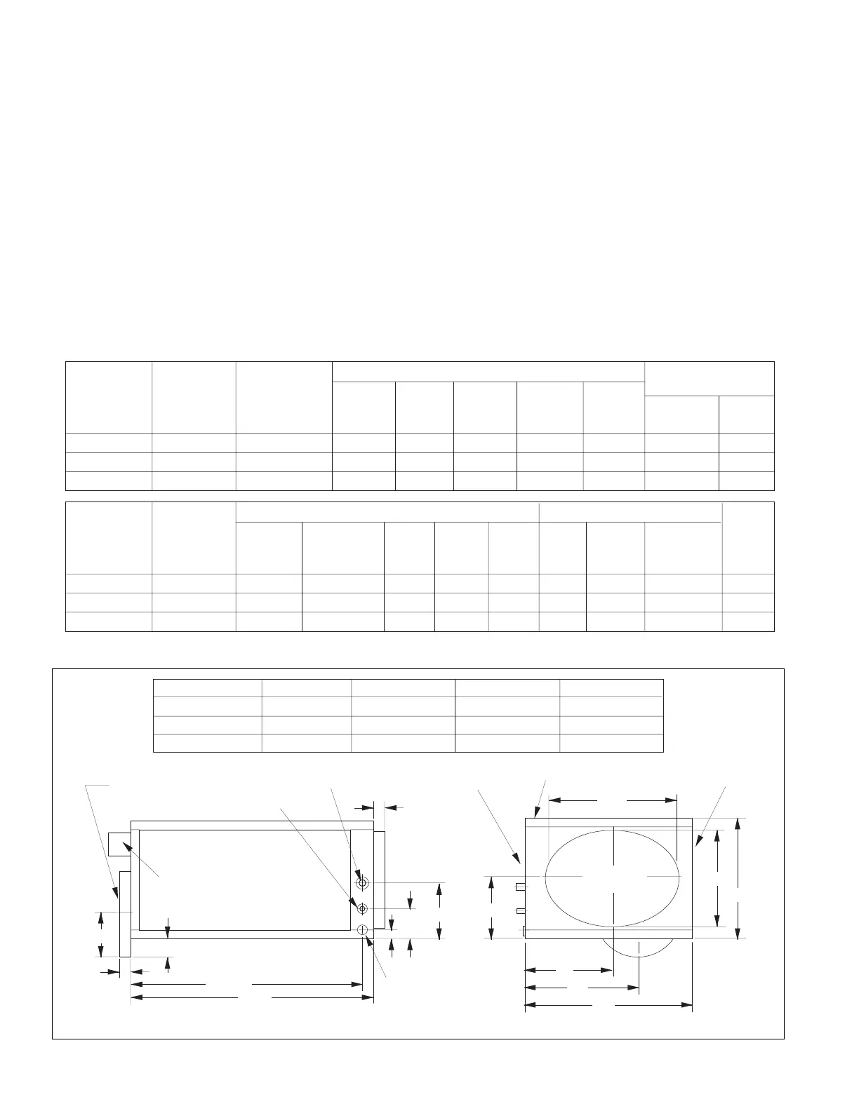
dimensions in Figure 2.2 and 2.3).
The fan coil unit is shipped in a horizontal air flow
arrangement, but can be easily field-converted to a
vertical air flow arrangement (see Figures 2.8 and 2.9).
When selecting a location, consider the locations as
shown in Figures 2.4, 2.5 and 2.6 of the return air box;
routing of the plenum duct, supply tubing, refrigerant
lines, condensate drain line; and all recommended
clearances (see Figures 2.2 and 2.3).
When installing unit in an attic (above a room ceiling),
recommend installing a secondary drain pan or optional
float switch. Follow local code requirements.
11-5/16"
6"
3-1/2"
1-5/8"
7"
1"
B
C
28-1/2"
30"
1-5/8"
5-1/2"
A
2-1/2"
D
14"
MODEL AB C
ESP-2430D
24-1/8"
12"
16-7/8"
ESP-3642D
33-1/8"
16-1/2"
24-1/4"
ESP-4860D
43-1/8"
21-1/2"
34-1/8"
D
15-3/8"
16-1/2"
21-1/2"
3/8" SWEAT (LIQUID)
7/8" SWEAT (SUCTION)
10-7/8" I.D.
SUPPLY
3/4" N.P.T.
DRAIN CONN.
8" MIN. CLEARANCE
12" MIN. CLEARANCE
38" MIN. CLEARANCE
ELECTRICAL
CONTROL BOX
RETURN
PLENUM
FIGURE 2.2: HORIZONTAL AIR FLOW UNIT DIMENSIONS AND CLEARANCES
Model
System
capacity
(Nom. Tons)
Suction
Line
Liquid
Line
Cond.
Drain
(NPT)
Return
Inlet
(Dia.)
Connections
Supply
Outlet
(I.D.)
Recommended
Condensing Unit
Capacity
(MBH)
Min
SEER
ESP-2430D
ESP-3642D
ESP-4860D
2 - 2-1/2
3 - 3-1/2
4 & 5
Electrical
Characteristics
1-60-208/230
1-60-208/230
1-60-208/230
7/8"
7/8"
7/8"
3/8"
3/8"
3/8"
3/4"
3/4"
3/4"
15"
19"
24"
9"
9"
9"
24 to 30
36 to 42
48 to 60
12+
12+
12+
Model
System
capacity
(Nom. Tons)
Std.
CFM @
1.5" W.C.
Motor
HP
F.L.
Amps
No. of
Rows
Deep
Blower
Refrig.
Charge
(R-22)
Flow
Control
Type
Ship.
Wt.
(lbs)
ESP-2430D
ESP-3642D
ESP-4860D
2 - 2-1/2
3 - 3-1/2
4 & 5
550 1/3
1/2
3/4
PSC
PSC
PSC
1.8
2.8
3.6
6
6
6
0 Exp. Valve
Exp. Valve
Exp. Valve
117
139
166
850
1150
Motor
Type
0
0
Coil
Wheel Dia.
and
Width
9" x 5"
9" x 6-3/8"
9" x 5"
FIGURE 2.1: MODEL ESP-D SPECIFICATIONS

Related product manuals