3
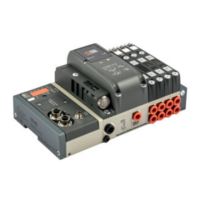
A Fixation par le dessus en utilisant les trous lisses des plaques
d’alimentation 1 ou 1-11 et de la plaque de fermeture.
B C Fixation par le dessous en utilisant les plaques d’alimentation 1 ou
1-11 et la plaque de fermeture, au moyen des taraudages M5
présents au dessous et à l’arrière des plaques.
D
Fixation par la face avant en utilisant les plaques d’alimentation 1 ou 1-11
et la plaque de fermeture, au moyen des taraudages M5 présents sur la face
des plaques. Une ouverture pour les tuyaux sera pratiquée dans le support.
E Fixation sur rail DIN avec les plaques d’alimentation 1 ou 1-11 et la
plaque de fermeture, au moyen des pattes code 0227301600.
F Fixation latérale, au moyen des taraudages M4 présents sur la
plaque de fermeture.
Nota: les seules fixations possibles sont celles indiquées ci-dessus.
FIXATION DE L’ILOT FIXING THE BASE
A Fixing from above using the 1 or 1-1 input terminal and the blind
terminal.
B C Fixing from above using the 1 or 1-1 input terminal and the blind
terminal, using the M5 threads on the bottom and the rear of the
terminals.
D Fixing from above using the 1 or 1-1 input terminal and the blind
terminal, using the M5 threads on the front of the terminals.
An opening for the pipes is made in the plate.
E Fixing on the DIN bar with end-plate 1 or 1-11 and blind and plate,
using the push-in bracket code 0227301600.
F Lateral fixing using the blind terminal, and its the M4 threads on the
side lateral.
Note: The sole fixing admitted is the one showed.
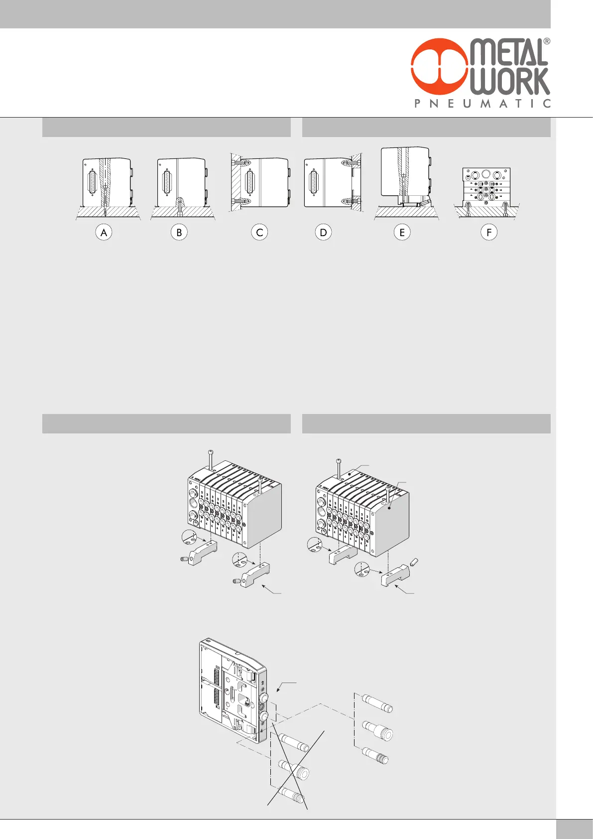
MONTAGE DES PATTES DE FIXATION
SUR RAIL DIN
Fixer les pattes sur la plaque de
fermeture a et sur la plaque
d’entrée b au moyen des vis
fournies.
Positionnement des pattes suivant Y
ou Z.
AUTRES INSTRUCTIONS DE MONTAGE GENERAL ASSEMBLY INSTRUCTIONS
FITTING THE CONNECTION
BRACKETS TO A DIN BAR
Fix the brackets both onto blind
terminal a and input terminal b
with the screws supplied.
Brackets positioning like Y or Z.
ø8
RL7 ø8
RL8 ø8/...
RL9 ø8
R7 ø8
R8 ø8/...
R9 ø8
NOTA
Pour tube ø8
NE PAS UTILISER LES RACCORDS
INSTANTANES TYPE R, MAIS
UNIQUEMENT LES RACCORDS DE
LA SERIE RL.
NOTE
For tube ø8
DO NOT USE R SERIES PUSH-IN
FITTINGS USE JUST RL SERIES
MINIATURE PUSH-IN FITTINGS
b
ZY
a

 Loading...