4
5
151 mm
301 mm
173 mm
5.1
5.2
5.3
5.5
5.4
5.7
5.6
5.9
5.8
5
EN
Technical data Functional description
Practice personnel, technicians
7. Technical data
Power supply 24 V AC
Frequency 50/60 Hz
Max. current consumption 4 A
Instrument fuse 6,3 A T
Max. power input 100 VA
Low pressure range 80 mbar - 160 mbar
Separation rate 96,4 %
Collection container volume 300 cm
3
Max. ambient temperature 40 °C
Possible suction systems wet or dry vacuum systems
Max. water ow rate
3.0 l/min at spittoon bowl
1.5 l/min at suction line
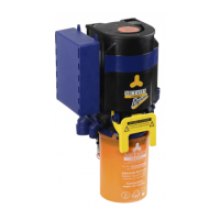
4
see illustration
total dimensions (HxWxD)
301 x 173 x 110 mm
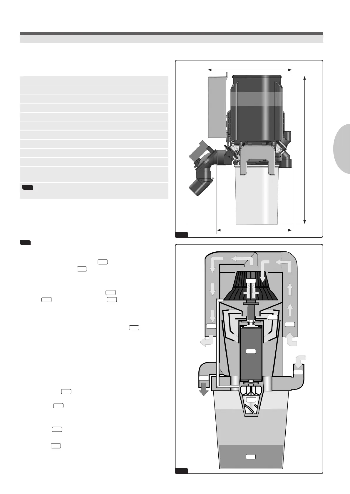
8. Functional description
5
See illustration
The waste water from the spittoon
5.6
is transported directly into
the collection container
5.1
which constitutes the rst phase
(sedimentation phase) of the amalgam separation process.
As soon as the level of liquid inside the collection container reaches the
range of the capacitive sensor, the motor
5.3
is started, which triggers
the pump
5.2
, as well as the centrifuge
5.4
and the rotor. The pump
pushes the water, which has been pre-cleaned through sedimentation,
into the centrifuge. Through the rotation of the centrifuge, the coarse
particles are ung to the walls of the two inner centrifuge chambers. The
cleaned water is continuously drained into the outlet
5.9
.
After one running period is over, the motor is short-circuited, which
causes the centrifuge to stop abruptly. Due to the continued rotation of
the water column, a self-cleaning effect takes place inside the centrifuge,
which rinses the heavy particles into the collection container.
When the suction hose is lifted off, the place selection valve is opened and
the motor is started. Thus, the pump, the centrifuge, and the separator
blades are set into rotation.
The suction current
5.7
is introduced through the separation chamber,
and is further accelerated in a circular manner by the fast rotating blades
of the air wheel
5.5
.
The solid and liquid constituents of the suction current are ejected
tangentially, while the air moves through the axis of the blades to the
suction engine
5.8
.
The ejected solid and liquid material is lead through a feeding hopper of
the centrifuge
5.4
and the above mentioned cycle starts again.