3
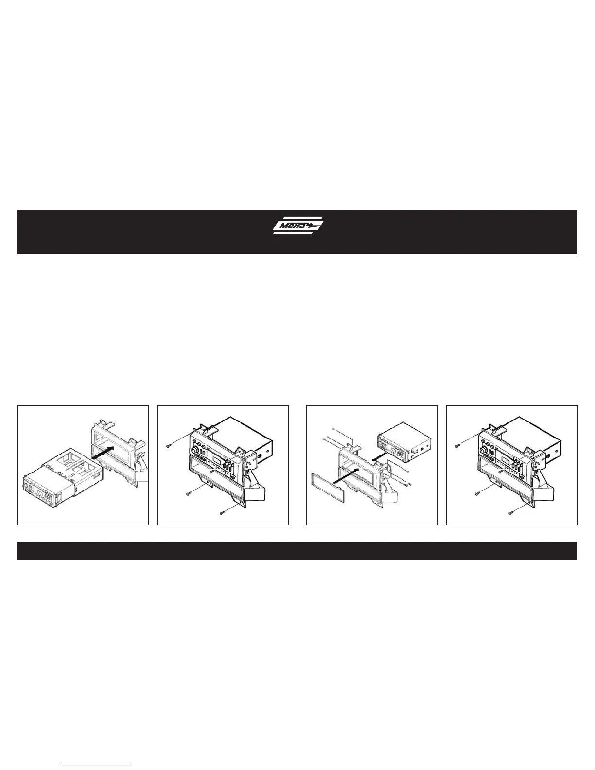
(Figure B)
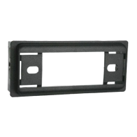
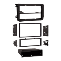
Kit Assembly
ISO DIN head unit provision
1. Snap the faceplate into the radio
housing. (Figure A)
2. Slide the aftermarket head unit into
the back of the kit. (Figure A)
3. Slide the ISO-DIN brackets onto the
housing legs and align the holes in the
brackets with the holes in the unit.
4. Mount the brackets to the unit with (4)
5 mm flat head screws supplied “A”.
(Figure A)
5. Mount the brackets to the top of the
housing legs with (2) #6 self-tapping
screws “B”. (Figure A)
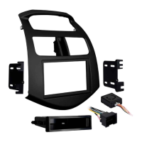
6. Locate the factory wiring harness in
the dash. Metra recommends using
the proper mating adapter from Metra
or AXXESS. Re-connect the negative
battery terminal and test the unit for
proper operation.
7. Mount the head unit/kit assembly
to the sub-dash with (4) screws
previously removed. (Figure B)
8. Reassemble dash in reverse order of
disassembly.
(Figure A)
“A”
“A”
“B”
“B”
(Figure B)
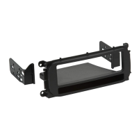
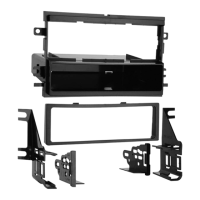
DIN head units provision
1. Slide the DIN cage into the kit and
secure by bending the metal locking
tabs down. (Figure A)
2. Slide the aftermarket head unit into
the cage until secure. (Figure A)
3. Locate the factory wiring harness in
the dash. Metra recommends using
the proper mating adapter from Metra
or AXXESS. Re-connect the negative
battery terminal and test the unit for
proper operation.
4. Mount the head unit/kit assembly
to the sub-dash with (4) screws
previously removed. (Figure B)
5. Reassemble dash in reverse order of
disassembly.
(Figure A)