Do you have a question about the Metra Electronics 99-3309B and is the answer not in the manual?
Procedure to unclip and remove the main radio trim panel from the factory dash.
Procedure to remove the four Phillips screws securing the factory radio from the dash.
Procedure to unclip and remove dashboard vents and the hazard button from the trim panel.
Procedure to remove five Phillips screws securing the upper display shroud from the factory panel.
Attach the factory vents and hazard button to the Metra trim panel.
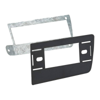
Attach the upper display shroud to the Metra trim panel using factory screws.
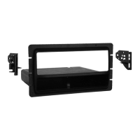
Attach the provided (10) panel clips to the legs of the Metra trim panel.
Locate factory wiring harness, use Metra adapter, reconnect battery, and test unit.
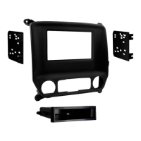
Attach radio brackets to aftermarket radio, then secure assembly to pocket using screws.
Mount the assembled radio unit into the vehicle's sub-dash.
Reassemble the dash using the Metra trim panel in reverse order of disassembly.
Attach the factory vents and hazard button to the Metra trim panel.
Attach the upper display shroud to the Metra trim panel using factory screws.
Attach the provided (10) panel clips to the legs of the Metra trim panel.
Locate factory wiring harness, use Metra adapter, reconnect battery, and test unit.
Attach radio brackets to aftermarket radio, then mount assembly into the sub-dash.
Reassemble the dash using the Metra trim panel in reverse order of disassembly.
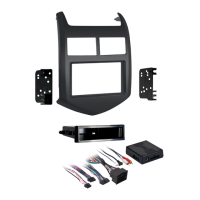
Details on interface features including accessory power, R.A.P., chimes, and NAV outputs.
Lists interface components like resistor pad harness and Camaro harness.
Connects 16-pin harness wires to aftermarket radio for ignition, illumination, amp turn-on, mute, and speakers.
Connects 44-way harness wires to aftermarket radio for ground, AUX, and 12V constant.
Connects Violet, Violet/Black, Green, Green/Black wires for rear speakers in amplified systems.
Connects specific wires and cuts resistors for non-amplified systems.
Plug the 16 and 22-pin harnesses into the interface, and connect vehicle/radio harnesses.
Steps to re-initialize the interface by cycling ignition if it loses power.
Procedure to adjust the chime volume using a potentiometer with the ignition on.
Procedure to adjust the audio level by turning the aftermarket radio and potentiometer.
Adjusts OnStar volume by grounding the Black/Yellow wire on the 16-pin harness.
Information on using the 12-pin harness in conjunction with the ASWC-1 for programming.
Using an optional LCD to adjust vehicle features like language.
| Brand | Metra Electronics |
|---|---|
| Model | 99-3309B |
| Category | Automobile Accessories |
| Language | English |