6.4 Installation process
6.4.1 Installation of the MQMe Quantometer
1. Clean the flange surfaces (e.g. with petroleum).
2. It is recommended to install the MQMe horizontally, with the meter index pointing upwards.
3. Ensure that the gas flow is in the direction of the arrow on the MQMe.
4. Ensure that the seals are mounted concentrically so that no seal parts protrude into the pipeline.
5. In addition to the length of the MQMe, provide enough room for the two gaskets between the inlet and outlet flanges
for the installation.
6. Install the MQMe without any tension. For this purpose, ensure that the meter axis is properly aligned with the pipeline
axis.
7. Carry out a proper leak test of the flange connections.
8. If necessary, turn the general direction of the meter display by 180°, see section 6.4.3“Changing the turning range”,
page 13.
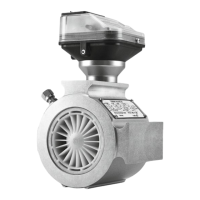
Screw connection on the meter index head for connecting an
equipotential bonding cable with a minimum cross-section of
Fig. 4: Connection for the equipotential bonding
6.4.2 Checkpoints during and after installation of the MQMe Quantometer
1. The MQMe is installed in the correct flow direction, see also section 6.2 “Installation location/direction of flow of the gas”,
page 10.
2. The MQMe has been installed without any leaks.
3. The MQMe has been installed without any tension.
‒
In a horizontal pipeline, the MQMe is installed with the meter index head in an upright position. In the case of vertical
installations, the oil pump (if present) must be installed in an upright position.
‒
Connection screws and nuts must be tightened crosswise.
‒
See section 12 “Measuring Points Pressure and Temperature”, page 29 for instructions on connecting to the pressure
measuring points.
‒
See section 12 “Measuring Points Pressure and Temperature”, page 29 for instructions on connecting to the
temperature measuring points.
4. The angle of rotation of the meter display corresponds to the operator’s requirements, see section 6.4.3“Changing the
turning range”, page 13.
We recommend a protective cover in the case of external installations.
12
 Loading...