12
B. MODULES — ALL MODULES
Your module has been designed to be user-
serviceable, assuming a basic knowledge of
the operation of electrical devices. This section
has been written to guide the user step by step,
and in layman’s terms, through the dismantling
and servicing of the module. Before attempting
to service your module, read the appropriate
Module Repair Procedures (found elsewhere in
this section) thoroughly. If you do not
understand the Repair Procedures or prefer not
to service your module yourself, or if your
warranty is still in effect, please contact our
Customer Service Department for the factory
authorized service agency nearest you.
DANGER: HAZARDOUS VOLTAGE.
DISCONNECT POWER BEFORE SERVICING
OR CLEANING.
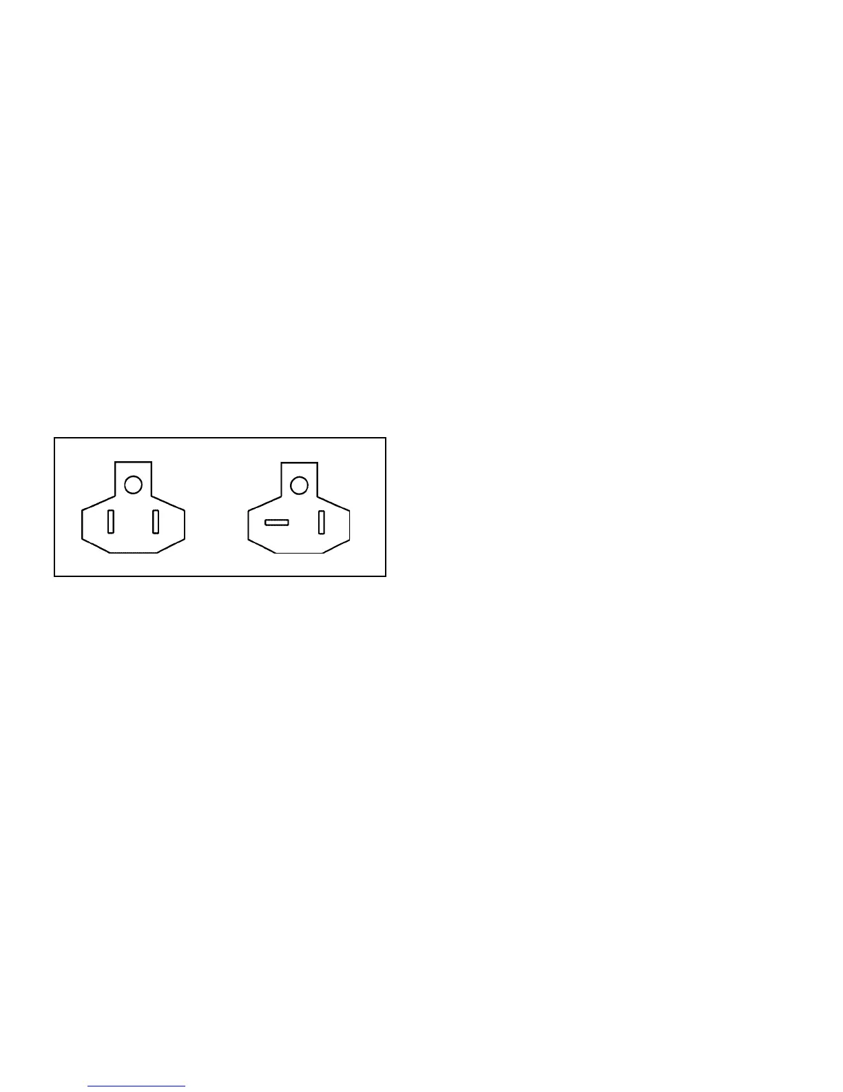
The lead cord plug configuration designates
whether your module uses a 15 or 20 amp
service. Refer to the illustration below to
identify the two different plugs.
15 AMP PLUG 20 AMP PLUG
PM2X675 HM2000, CM2000
MODULES MODULES
CAUTION: IT IS IMPORTANT THAT ALL
SAFETY PRECAUTIONS PERTAINING TO
THE SERVICING OF ELECTRICAL
DEVICES BE OBSERVED AT ALL TIMES.
1. Dismantle your module for servicing per the
following instructions.
NOTE: To replace the Thermostat Knob or water
pan, it is not necessary to dismantle the module.
a. Make sure the lead cord is not plugged into
an outlet. Be certain that the module and any
water in the water pan has cooled to a
temperature safe for handling.
b.Remove module by lifting the front
enough to clear the detent, then pull the
module from the cabinet, grasping it with
both hands as it clears the cabinet. The
cord should slip through the clearance
hole in the back of the cabinet.
c. Remove the water pan and drain water
from pan.
d. Unfasten the electrical cover by removing the
three screws along the front of the module
and the two screws along each edge of the
module. Retain this hardware for re-assembly.
e. Open the module by raising the
component chassis from the electrical
cover and placing the chassis top down
on a dry, non-flammable work surface. IF
NECESSARY TO RECONNECT THE
OPENED MODULE TO A POWER
SOURCE, PRACTICE EXTREME CAUTION
SO AS NOT TO RECEIVE ELECTRICAL
SHOCK FROM EXPOSED COMPONENTS.
2. Refer to the appropriate Module
Replacement Parts Diagram to identify the
internal components. Determine
malfunctioning component(s) by electrical
diagnostic procedures.
3.After servicing, be sure to verify the routing
of each wire with the appropriate wiring
schematic before installing electrical cover
and connecting module to power source.
Be sure that the thermostat sensor tube
does not contact any electrical connections.
4. Assemble components using the retained
hardware, making sure that no wires are
pinched between the cover and the
component chassis.
5. Install water pan. Then, feed cord through
clearance hole in cabinet and slide module
into cabinet.
 Loading...